
Page 611 - The Mechatronics Handbook
P. 611
0066_Frame_C20 Page 81 Wednesday, January 9, 2002 5:49 PM
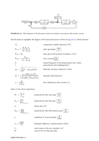
FIGURE 20.112 Block diagram of the linearized model of an hydraulic servosystem with position control.
that the leaks are negligible, the diagram of the linearized system is shown in Fig. 20.112, which indicates:
compensator transfer function [V/V]
G C
m/s
K OLV = ------------------------ static speed gain ---------
K′ S K Q A C
2
A C – K PQ g V
K TP = K R static gain of the position transducer [V/m]
m
K OLF = ------------------------ force constant ------
K PQ
2
A C – K PQ g sN
natural frequency of the proportional valve [rad/s]
σ n
ζ proportional valve damping factor
s A = ----- 1 (–[ K PQ g/A C )] hydraulic resonance frequency [rad/s]
2
C 0
M
g ( MK PQ C 0 /A C )
2
–
z A = -------------------------------------------------------- hydraulic damping factor
[
2 C 0 M 1 ( K PQ g/A C )]
2
–
2
t = --------------- force disturbance time constant [s]
A C
C 0 K PQ
where, in the above expressions:
2
m
K′ S = A Vmax proportional valve static gain ------
-------------
V max V
3
m
∂Q
K Q = --------- proportional valve flow gain ---------- 2
∂A V A ,P s m
V0 L0
2
piston area [m ]
A C
3
m
∂
Q
K PQ = -------- proportional valve flow-pressure gain ---------
∂ P L A ,P s Pa
V0 L0
N
γ coefficient of viscous friction ---------
s/m
2
4bA C
C 0 = ------------- hydraulic stiffness in centred position [N/m]
V T
3
total volume of the two chambers [m ]
V T
M mass of the moving parts [kg]
©2002 CRC Press LLC