
Page 615 - The Mechatronics Handbook
P. 615
0066_Frame_C20 Page 85 Wednesday, January 9, 2002 5:49 PM
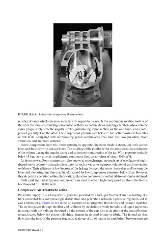
FIGURE 20.115 Rotary vane compressor (Pneumofore).
number of vanes which can move radially with respect to its axis. In the continuous rotation motion of
the rotor, the vanes are centrifuged in contact with the seat of the stator, isolating chambers whose volume
varies progressively with the angular stroke, guaranteeing input suction on the one hand, and a com-
pressed gas output on the other. The compression pressures are below 15 bar, with maximum flow rates
3
of 500 m /h. Compared with reciprocating piston compressors, they have less flow pulsation, fewer
vibrations, and are more compact.
Screw compressors have two rotors rotating in opposite directions inside a stator, one with convex
lobes and the other with concave lobes. The coupling of the profiles of the two rotors leads to a reduction
of the volume during the angular stroke and consequent compression of the gas. With pressures typically
3
below 15 bar, they provide a sufficiently continuous flow, up to values of about 3000 m /h.
In the same way, Roots compressors, also known as superchargers, are made up of two figure-of-eight-
shaped rotors counter-rotating inside a stator in such a way as to transport volumes of gas from suction
to delivery. Their efficiency is low because of the leakage between the rotors themselves and between the
lobes and the casing, and they are, therefore, used for low compression pressures, below 2 bar. However,
they do permit operation without lubrication, like screw compressors, so that oil-free air can be obtained.
Both axial and radial dynamic compressors are used to obtain high compressed air flow rates from a
3
few thousand to 100,000 m /h.
Compressed Air Treatment Units
Pneumatic supply to a servosystem is generally provided by a local gas treatment unit, consisting of a
filter, connected to a compressed gas distribution and generation network, a pressure regulator, and in
case a lubricator L. Figure 20.116 shows an example of an integrated filter device and pressure regulator.
The air first passes through the filter and is filtered by the deflector while the solid and liquid impurities
in contact with the walls are deposited on the bottom of the cup, also as an effect of the conical bottom
screen, located below the porous cylindrical element in sintered bronze or fabric. The filtered air then
flows into the inlet of the pressure regulator, made up of an obturator in equilibrium between pressure
©2002 CRC Press LLC