
Page 620 - The Mechatronics Handbook
P. 620
0066_Frame_C20 Page 90 Wednesday, January 9, 2002 5:49 PM
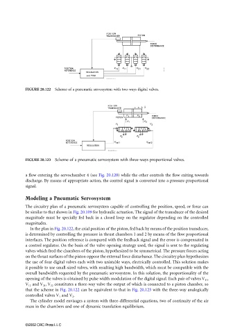
FIGURE 20.122 Scheme of a pneumatic servosystem with two-ways digital valves.
FIGURE 20.123 Scheme of a pneumatic servosystem with three-ways proportional valves.
a flow entering the servochamber 4 (see Fig. 20.120) while the other controls the flow exiting towards
discharge. By means of appropriate action, the control signal is converted into a pressure proportional
signal.
Modeling a Pneumatic Servosystem
The circuitry plan of a pneumatic servosystem capable of controlling the position, speed, or force can
be similar to that shown in Fig. 20.109 for hydraulic actuation. The signal of the transducer of the desired
magnitude must be specially fed back in a closed loop on the regulator depending on the controlled
magnitudes.
In the plan in Fig. 20.122, the axial position of the piston, fed back by means of the position transducer,
is determined by controlling the pressure in thrust chambers 1 and 2 by means of the flow proportional
interfaces. The position reference is compared with the feedback signal and the error is compensated in
a control regulator. On the basis of the valve opening strategy used, the signal is sent to the regulating
valves which feed the chambers of the piston, hypothesized to be symmetrical. The pressure forces acting
on the thrust surfaces of the piston oppose the external force disturbance. The circuitry plan hypothesizes
the use of four digital valves each with two unistable ways, electrically controlled. This solution makes
it possible to use small-sized valves, with resulting high bandwidth, which must be compatible with the
overall bandwidth requested by the pneumatic servosystem. In this solution, the proportionality of the
opening of the valves is obtained by pulse width modulation of the digital signal. Each pair of valves V 11 ,
V 12 and V 21 , V 22 constitutes a three-way valve the output of which is connected to a piston chamber, so
that the scheme in Fig. 20.122 can be equivalent to that in Fig. 20.123 with the three-way analogically
controlled valves V 1 and V 2 .
The cylinder model envisages a system with three-differential equations, two of continuity of the air
mass in the chambers and one of dynamic translation equilibrium.
©2002 CRC Press LLC