
Page 619 - The Mechatronics Handbook
P. 619
0066_Frame_C20 Page 89 Wednesday, January 9, 2002 5:49 PM
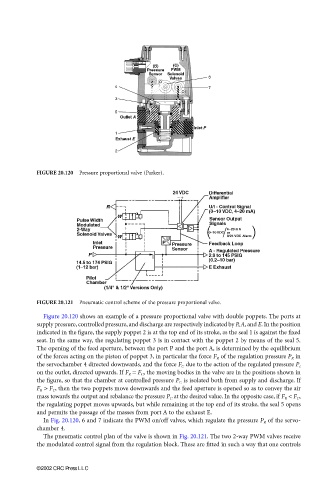
FIGURE 20.120 Pressure proportional valve (Parker).
FIGURE 20.121 Pneumatic control scheme of the pressure proportional valve.
Figure 20.120 shows an example of a pressure proportional valve with double poppets. The ports at
supply pressure, controlled pressure, and discharge are respectively indicated by P, A, and E. In the position
indicated in the figure, the supply poppet 2 is at the top end of its stroke, as the seal 1 is against the fixed
seat. In the same way, the regulating poppet 3 is in contact with the poppet 2 by means of the seal 5.
The opening of the feed aperture, between the port P and the port A, is determined by the equilibrium
of the forces acting on the piston of poppet 3, in particular the force F R of the regulation pressure P R in
the servochamber 4 directed downwards, and the force F C due to the action of the regulated pressure P c
on the outlet, directed upwards. If F R = F C , the moving bodies in the valve are in the positions shown in
the figure, so that the chamber at controlled pressure P C is isolated both from supply and discharge. If
F R > F C , then the two poppets move downwards and the feed aperture is opened so as to convey the air
mass towards the output and rebalance the pressure P C at the desired value. In the opposite case, if F R < F C ,
the regulating poppet moves upwards, but while remaining at the top end of its stroke, the seal 5 opens
and permits the passage of the masses from port A to the exhaust E.
In Fig. 20.120, 6 and 7 indicate the PWM on/off valves, which regulate the pressure P R of the servo-
chamber 4.
The pneumatic control plan of the valve is shown in Fig. 20.121. The two 2-way PWM valves receive
the modulated control signal from the regulation block. These are fitted in such a way that one controls
©2002 CRC Press LLC