
Page 617 - The Mechatronics Handbook
P. 617
0066_Frame_C20 Page 87 Wednesday, January 9, 2002 5:49 PM
As far as pressure regulation valves are concerned, three-way pressure proportional valves are available
for pneumatic actuation which convert an electrical reference signal with standardized input into a
controlled output pressure with good dynamics and high precision.
PWM (Pulse Width Modulation) Valves
The structure of PWM valves is similar to the corresponding electrically controlled unistable digital
valves, but uses a technique for modulating the width of the pulses sent to the solenoid for supplying
proportional control of the flow rate. This technique envisages that the input voltage reference analog
signal V REF (for example 0–10 V) is converted by a special driver into a digital V PWM (ON/OFF) signal
with pulse duration proportional to the input signal. Alternatively, the modulated signal can be generated
directly by a digital controller, such as a PLC.
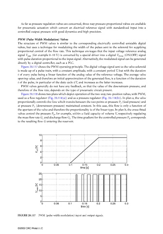
Figure 20.117 shows the PWM operating principle. The digital voltage signal sent to the valve solenoid
is made up of a pulse train, with a constant amplitude, with a constant period T, but with the duration
t of every pulse being a linear function of the analog value of the reference voltage. The average valve
opening value, and therefore an initial approximation of the generated flow, is a function of the duration
t of the pulse, in particular of the duty cycle t/T, and increases as the latter increases.
PWM valves generally do not have any feedback, so that the value of the downstream pressure, and
therefore of the flow rate, depends on the type of pneumatic circuit present.
Figure 20.118 shows two plans which depict operation of the two-way, two-position valves, with PWM,
used as a flow regulator (Fig. 20.118(a)) and as a pressure regulator (Fig. 20.118(b)). In plan a, the valve
proportionally controls the flow which transits between the two points at pressure P S (feed pressure) and
at pressure P V (downstream pressure) maintained constant. In this case, this flow is only a function of
the aperture of the valve and therefore the proportionality is of the linear type. In plan b, the cross-fitted
valves control the pressure P R , for example, within a fluid capacity of volume V, respectively regulating
the mass flow rate G 1 and discharge flow G 2 . The time gradient for the controlled pressure P R corresponds
to the resulting flow G entering the reservoir.
FIGURE 20.117 PWM (pulse width modulation) input and output signals.
©2002 CRC Press LLC