
Page 625 - The Mechatronics Handbook
P. 625
0066_Frame_C20 Page 95 Wednesday, January 9, 2002 5:49 PM
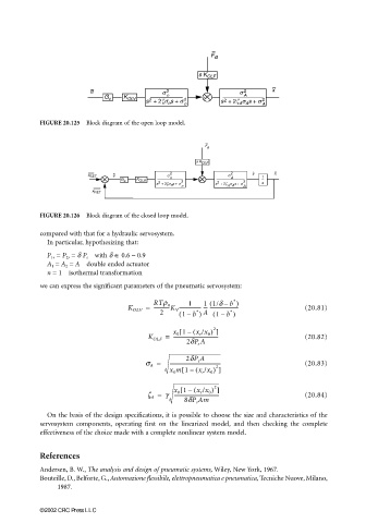
FIGURE 20.125 Block diagram of the open loop model.
FIGURE 20.126 Block diagram of the closed loop model.
compared with that for a hydraulic servosystem.
In particular, hypothesizing that:
with δ ∈ 0.6 – 0.9
P 1r = P 2r = δ P s
A 1 = A 2 = A double ended actuator
n = 1 isothermal transformation
we can express the significant parameters of the pneumatic servosystem:
∗
(
1 1/d b )
1
–
K OLV = RTr n ------------------ --- ------------------------ (20.81)
∗
∗
-------------K V
2 ( 1 b ) A ( 1 b )
–
–
[
x 0 1 ( x r /x 0 ) ]
2
–
K OLF = ------------------------------------- (20.82)
2dP s A
2dP s A
s A = ------------------------------------------ (20.83)
x 0 m 1 ( x r /x 0 ) ]
[
2
–
x 0 1 (–[ x r /x 0 ) ]
2
z A = g ------------------------------------- (20.84)
8dP s Am
On the basis of the design specifications, it is possible to choose the size and characteristics of the
servosystem components, operating first on the linearized model, and then checking the complete
effectiveness of the choice made with a complete nonlinear system model.
References
Andersen, B. W., The analysis and design of pneumatic systems, Wiley, New York, 1967.
Bouteille, D., Belforte, G., Automazione flessibile, elettropneumatica e pneumatica, Tecniche Nuove, Milano,
1987.
©2002 CRC Press LLC