Page 629 - The Mechatronics Handbook
P. 629
0066_Frame_C20.fm  Page 99  Wednesday, January 9, 2002  1:44 PM


                                                               2
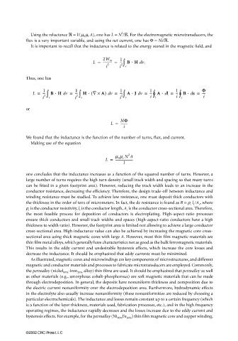
                         Using the reluctance ℜ = l/(µ 0 µ r A), one has L = N /ℜ. For the electromagnetic microtransducers, the
                       flux is a very important variable, and using the net current, one has Φ = Ni/ℜ.
                         It is important to recall that the inductance is related to the energy stored in the magnetic field, and


                                                              1
                                                               2∫
                                                   L =  ----------- =  --- B ⋅⋅ ⋅⋅ H  v.d
                                                       2W m
                                                         i 2  i  v
                       Thus, one has

                              1
                                                                                       ∫
                                                                            ∫
                                                              --- A ⋅⋅ ⋅⋅ J  vd =
                                                  (
                         L =  --- 2∫  B ⋅⋅ ⋅⋅ H  v =  1 2∫  H ⋅⋅ ⋅⋅  ∇ ×  A)  v =  1 2∫  1 i °  A ⋅⋅ ⋅⋅  l =  1 i °  B ⋅⋅ ⋅⋅  s =  Φ
                                                                                            d
                                                                                      --
                                           ---
                                                                                                 ----
                                      d
                                                         d
                                                                           --
                                                                                 d
                              i  v         i  v               i  v           l          s         i
                       or
                                                          L =  NΦ
                                                               ---------
                                                                i
                       We found that the inductance is the function of the number of turns, flux, and current.
                         Making use of the equation
                                                                  2
                                                            m 0 m r N A
                                                        L =  ----------------------
                                                                l
                       one concludes that the inductance increases as a function of the squared number of turns. However, a
                       large number of turns requires the high turn density (small track width and spacing so that many turns
                       can be fitted in a given footprint area). However, reducing the track width leads to an increase in the
                       conductor resistance, decreasing the efficiency. Therefore, the design trade-off between inductance and
                       winding resistance must be studied. To achieve low resistance, one must deposit thick conductors with
                       the thickness in the order of tens of micrometers. In fact, the dc resistance is found as R = ρ c  l c /A c , where
                       ρ c  is the conductor resistivity, l c  is the conductor length, A c  is the conductor cross-sectional area. Therefore,
                       the most feasible process for deposition of conductors is electroplating. High-aspect-ratio processes
                       ensure thick conductors and small track widths and spaces (high-aspect-ratio conductors have a high
                       thickness to width ratio). However, the footprint area is limited not allowing to achieve a large conductor
                       cross-sectional area. High inductance value can also be achieved by increasing the magnetic core cross-
                       sectional area using thick magnetic cores with large A. However, most thin film magnetic materials are
                       thin film metal alloys, which generally have characteristics not as good as the bulk ferromagnetic materials.
                       This results in the eddy current and undesirable hysteresis effects, which increase the core losses and
                       decrease the inductance. It should be emphasized that eddy currents must be minimized.
                         As illustrated, magnetic cores and microwindings are key components of microstructures, and different
                       magnetic and conductor materials and processes to fabricate microtransducers are employed. Commonly,
                       the permalloy (nickel 80% -iron 20%  alloy) thin films are used. It should be emphasized that permalloy as well
                       as other materials (e.g., amorphous cobalt-phosphorous) are soft magnetic materials that can be made
                       through electrodeposition. In general, the deposits have nonuniform thickness and composition due to
                       the electric current nonuniformity over the electrodeposition area. Furthermore, hydrodynamic effects
                       in the electrolyte also usually increase nonuniformity (these nonuniformities are reduced by choosing a
                       particular electrochemicals). The inductance and losses remain constant up to a certain frequency (which
                       is a function of the layer thickness, materials used, fabrication processes, etc.), and in the high frequency
                       operating regimes, the inductance rapidly decreases and the losses increase due to the eddy current and
                       hysteresis effects. For example, for the permalloy (Ni 80% Fe 20% ) thin film magnetic core and copper winding,


                       ©2002 CRC Press LLC

