
Page 628 - The Mechatronics Handbook
P. 628
0066_Frame_C20.fm Page 98 Wednesday, January 9, 2002 1:44 PM
Closed-Ended Open-Ended
Electromagnetic System Electromagnetic System
,
m r s Magnetic Core
r, L
Displacement
i
a
u a Microwindings
Silicon Substrate
Magnetic Core
Electroplated Magnetic Core
with Copper Microwindings Copper Windings
r , L
Insulator
m r , s
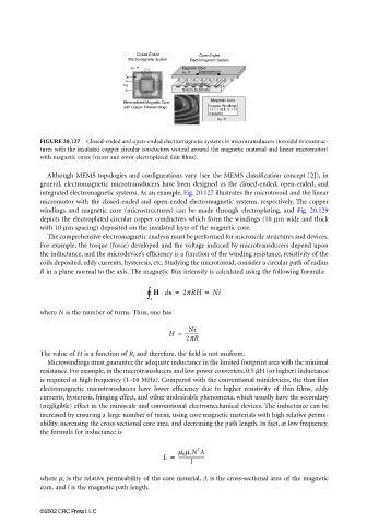
FIGURE 20.127 Closed-ended and open-ended electromagnetic systems in microtransducers (toroidal microstruc-
tures with the insulated copper circular conductors wound around the magnetic material and linear micromotor)
with magnetic cores (stator and rotor electroplated thin films).
Although MEMS topologies and configurations vary (see the MEMS classification concept [2]), in
general, electromagnetic microtransducers have been designed as the closed-ended, open-ended, and
integrated electromagnetic systems. As an example, Fig. 20.127 illustrates the microtoroid and the linear
micromotor with the closed-ended and open-ended electromagnetic systems, respectively. The copper
windings and magnetic core (microstructures) can be made through electroplating, and Fig. 20.129
depicts the electroplated circular copper conductors which form the windings (10 mm wide and thick
with 10 mm spacing) deposited on the insulated layer of the magnetic core.
The comprehensive electromagnetic analysis must be performed for microscale structures and devices.
For example, the torque (force) developed and the voltage induced by microtransducers depend upon
the inductance, and the microdevice’s efficiency is a function of the winding resistance, resistivity of the
coils deposited, eddy currents, hysteresis, etc. Studying the microtoroid, consider a circular path of radius
R in a plane normal to the axis. The magnetic flux intensity is calculated using the following formula:
∫ s ° H ds = 2pRH = Ni
⋅
where N is the number of turns. Thus, one has
Ni
H = ----------
2pR
The value of H is a function of R, and therefore, the field is not uniform.
Microwindings must guarantee the adequate inductance in the limited footprint area with the minimal
resistance. For example, in the microtransducers and low power converters, 0.5 µH (or higher) inductance
is required at high frequency (1–10 MHz). Compared with the conventional minidevices, the thin film
electromagnetic microtransducers have lower efficiency due to higher resistivity of thin films, eddy
currents, hysteresis, fringing effect, and other undesirable phenomena, which usually have the secondary
(negligible) effect in the miniscale and conventional electromechanical devices. The inductance can be
increased by ensuring a large number of turns, using core magnetic materials with high relative perme-
ability, increasing the cross-sectional core area, and decreasing the path length. In fact, at low frequency,
the formula for inductance is
2
m 0 m r N A
L = ---------------------
l
where µ r is the relative permeability of the core material, A is the cross-sectional area of the magnetic
core, and l is the magnetic path length.
©2002 CRC Press LLC