
Page 633 - The Mechatronics Handbook
P. 633
0066_Frame_C20.fm Page 103 Wednesday, January 9, 2002 1:44 PM
Augmenting this equation with the differential equation and the torsional-mechanical dynamics
2
d x
------ +
Ft() = m-------- + B v dx ( k s1 x + k s2 x ) + F e t()
2
dt 2 dt
three nonlinear differential equations for the considered translational microtransducer are found to be
(
(
di rA g l f +[ 2A f m f x + 2d)] 2m f A f A g l f + 2A f m f x + 2d)
----- = – --------------------------------------------------------i + -------------------------------------------------iv + -------------------------------------------------u a
(
dt 2 A g l f + 2A f m f x + 2d) 2
N m f m 0 A f A g N m f m 0 A f A g
2 2 2
dv N m f m 0 A f A g 2 1 2 B v
----- = -------------------------------------------------------------i – ---- k s1 x +( k s2 x ) – -----v
[
(
dt mA g l f + 2A f m f x + 2d)] 2 m m
dx
------ = v
dt
The derived differential equations represent the lumped-parameter mathematical model of the
microtransducer. Although, in general, the high-fidelity modeling must be performed integrating nonlin-
earities (for example, nonlinear magnetic characteristics and hysteresis) and secondary effects, the
lumped-parameter mathematical models as given in the form of nonlinear differential equations have
been validated for microtransducers. It is found that the major phenomena and effects are modeled for
the current, velocity, and displacement (secondary effects such as Coulomb friction, hysteresis and eddy
currents, fringing effect and other phenomena have not been modeled and analyzed). However, the
lumped-parameter modeling provides one with the capabilities to attain reliable preliminary steady-state
and dynamic analysis using primary circuitry and mechanical variables. It is also important to emphasize
that the voltage, applied to the microwinding, is regulated by ICs. The majority of ICs to control
microtransducers are designed using the pulse-width-modulation topologies. The switching frequency
of ICs is usually 1 MHz or higher. Therefore, as was shown, it is very important to study the microtrans-
ducer performance at the high operating frequency. This can be performed using Maxwell’s equations,
which will lead to the high-fidelity mathematical models [2].
Single-Phase Reluctance Micromotors: Microfabrication,
Modeling, and Analysis
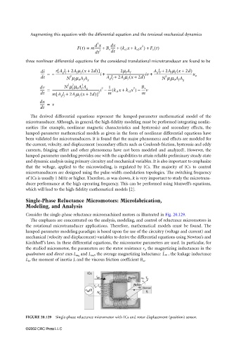
Consider the single-phase reluctance micromachined motors as illustrated in Fig. 20.129.
The emphases are concentrated on the analysis, modeling, and control of reluctance micromotors in
the rotational microtransducer applications. Therefore, mathematical models must be found. The
lumped-parameter modeling paradigm is based upon the use of the circuitry (voltage and current) and
mechanical (velocity and displacement) variables to derive the differential equations using Newton’s and
Kirchhoff’s laws. In these differential equations, the micromotor parameters are used. In particular, for
the studied micromotor, the parameters are the stator resistance r s , the magnetizing inductances in the
, the leakage inductance
quadrature and direct axes L mq and L md , the average magnetizing inductance L m
L ls , the moment of inertia J, and the viscous friction coefficient B m .
FIGURE 20.129 Single-phase reluctance micromotor with ICs and rotor displacement (position) sensor.
©2002 CRC Press LLC