Page 636 - The Mechatronics Handbook
P. 636

0066_Frame_C20.fm  Page 106  Wednesday, January 9, 2002  1:46 PM


                         The micromachine parameters are the stator resistance r s , the magnetizing inductances in the quadra-
                                                                              , the leakage inductance L ls , the
                       ture and direct axes L mq  and L md , the average magnetizing inductance L m
                       moment of inertia J, and the viscous friction coefficient B m .
                         The expressions for inductances are nonlinear functions of the electrical angular displacement  θ r .
                       Hence, the  torsional-mechanical dynamics must be used. Taking note of the Newton’s second law of
                       rotational motion, and using ω r  and θ r  (electrical angular velocity and displacement) as the state variables
                       (mechanical variables), one obtains
                                                    2          2 dw r  dq r
                                              T e –  B m ---w r –  T L =  J --- ---------,  -------- =  w r
                                                    P          P dt    dt
                       where T e  and T L  are the electromagnetic and load torques.
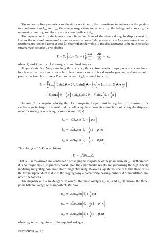
                         Torque Production  Analysis—Using the coenergy, the electromagnetic torque, which is a nonlinear
                       function of the micromotor variables (phase currents and electrical angular position) and micromotor
                       parameters (number of poles P and inductance L ∆m ), is found to be [8],
                                                                      
                                                               
                                                                                 
                                   T e =  P   2   2q r +  2i as i bs sin 2 q r –  1 --p +  2i as i cs sin 2 q r +  1  
                                                                                      --p
                                        ---L ∆m i as sin
                                        2                          3               3 

                                               
                                                                          
                                          2
                                                   --p +
                                                                     2
                                        +  i bs sin 2 q r –  2    2i bs i cs sin 2q r +  i cs sin 2 q r +  2  
                                                                               --p
                                                                               3 
                                                   3 
                                                                          
                                               
                         To control the angular velocity, the electromagnetic torque must be regulated. To maximize the
                       electromagnetic torque, ICs must feed the following phase currents as functions of the angular displace-
                       ment measuring or observing (sensorless control) θ r
                                                 i as =  2i M sin  q r +  1 --j i p
                                                                  3
                                                 i bs =  2i M sin  q r –  1 (  –
                                                                 -- 2 j i )p
                                                                 3
                                                 i cs =  2i M sin  q r +  1 -- 2 +(  j i )p
                                                                  3
                       Thus, for ϕ i  = 0.3245, one obtains
                                                                    2
                                                       T e =  2PL ∆m i M
                       That is, T e  is maximized and controlled by changing the magnitude of the phase currents i M . Furthermore,
                       it is no torque ripple (in practice, based upon the experimental results, and performing the high-fidelity
                       modeling integrating nonlinear electromagnetics using Maxwell’s equations, one finds that there exists
                       the torque ripple which is due to the cogging torque, eccentricity, bearing, pulse-width-modulation, and
                       other phenomena).
                         The majority of ICs are designed to control the phase voltages u as , u bs , and u cs . Therefore, the three-
                       phase balance voltage set is important. We have

                                                 u as =  2u M sin  q r +  1
                                                                  --j i p
                                                                  3
                                                 u bs =  2u M sin  q r –  1 -- 2 j i )p
                                                                   (
                                                                     –
                                                                  3
                                                                  -- 2 +(
                                                 u cs =  2u M sin  q r +  1  j i )p
                                                                  3
                       where u M  is the magnitude of the supplied voltages.


                       ©2002 CRC Press LLC
   631   632   633   634   635   636   637   638   639   640   641