Page 638 - The Mechatronics Handbook
P. 638

0066_Frame_C20.fm  Page 108  Wednesday, January 9, 2002  1:46 PM


                       Here

                                                                                                 2
                               -- L mq +(
                                                                           (
                         L m =  1    L md ),  L ∆m =  1  L mq )  and  L D =  L ls 9L ∆m –  4L ls –  12L mL ls –  9L m)
                                                  -- L md –(
                                                                                    2
                                                                              2
                               3                  3
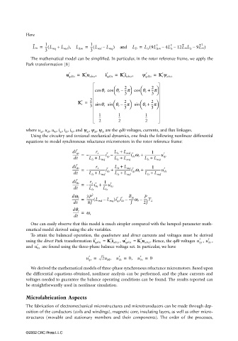
                         The mathematical model can be simplified. In particular, in the rotor reference frame, we apply the
                       Park transformation [8]
                                                r
                                         r
                                                                         r
                                                                                r
                                                                r
                                                         r
                                        u qd0s =  K s u abcs ,  i qd0s =  K s i abcs ,  y qd0s =  K s y abcs
                                                               2         2  
                                                    cos q r cos  q r –  --p cos  q r +  --p
                                                                3 
                                                                            3 
                                              r   2             2           2
                                             K s =  --  sin q r sin  q r –  --p   sin  q r +  --p 
                                                  3            3         3 
                                                     1        1          1
                                                     --       --         --
                                                     2        2          2
                       where u qs , u ds , u 0s , i qs , i ds , i 0s , and ψ qs , ψ ds , ψ 0s  are the qd0 voltages, currents, and flux linkages.
                         Using the circuitry and torsional-mechanical dynamics, one finds the following nonlinear differential
                       equations to model synchronous reluctance micromotors in the rotor reference frame:
                                            r               L ls +
                                                                            1
                                          -------- =  – --------------------i qs –  --------------------i ds w r +  --------------------u qs
                                                                                 r
                                                                L md r
                                                         r
                                                    r s
                                          di qs
                                           dt    L ls +  L mq  L ls +  L mq  L ls +  L mq
                                            r               L ls +
                                                                            1
                                          -------- =  – --------------------i ds +  --------------------i qs w r +  --------------------u ds
                                          di ds
                                                    r s
                                                         r
                                                                L mq r
                                                                                 r
                                           dt    L ls +  L md  L ls +  L md  L ls +  L md
                                            r
                                                        1
                                          -------- =  – -----i 0s +  -----u 0s
                                          di 0s
                                                          r
                                                  r s r
                                           dt    L ls  L ls
                                                  2
                                                                         P
                                                             r
                                                               r
                                          --------- =  3P  L mq )i qs i ds –  B m  -----T L
                                                -------- L md –(
                                          dw r
                                                                  ------w r –
                                           dt    8J                J    2J
                                          -------- =  w r
                                          dq r
                                           dt
                         One can easily observe that this model is much simpler compared with the lumped-parameter math-
                       ematical model derived using the abc variables.
                         To attain the balanced operation, the quadrature and direct currents and voltages must be derived
                                                    r     r      r     r                        r   r
                                                              ,
                                                                                                  ,
                       using the direct Park transformation  i qd0s   = K s i abcs u qd0s  = K s u abcs . Hence, the qd0 voltages u qs u ds  ,
                           r
                       and  u 0s   are found using the three-phase balance voltage set. In particular, we have
                                                              r
                                                 r
                                                                       r
                                                u qs =  2u M ,  u ds =  0,  u 0s =  0
                         We derived the mathematical models of three-phase synchronous reluctance micromotors. Based upon
                       the differential equations obtained, nonlinear analysis can be performed, and the phase currents and
                       voltages needed to guarantee the balance operating conditions can be found. The results reported can
                       be straightforwardly used in nonlinear simulation.
                       Microfabrication Aspects
                       The fabrication of electromechanical microstructures and microtransducers can be made through dep-
                       osition of the conductors (coils and windings), magnetic core, insulating layers, as well as other micro-
                       structures (movable and stationary members and their components). The order of the processes,
                       ©2002 CRC Press LLC
   633   634   635   636   637   638   639   640   641   642   643