Page 634 - The Mechatronics Handbook
P. 634
0066_Frame_C20.fm  Page 104  Wednesday, January 9, 2002  1:44 PM


                         The expression for the electromagnetic torque was derived in [8]. In particular,

                                                       T e =  L ∆m i as sin  2q r
                                                               2

                       where L ∆m  is the half-magnitude of the sinusoidal magnetizing inductance L m  variations,
                                                      ()
                                                    L m q r =  L m –  L ∆m cos  2q r
                         Thus, to develop the electromagnetic torque, the current i as  must be fed as a function of the rotor
                       angular displacement θ r . For example, if i as  = i M Re( sin  2q r  ), then

                                                      1
                                             T eaverage =  --- ∫  p L ∆m i as sin 2q r   q r =  1  2
                                                             2
                                                                    d
                                                                          --L ∆m i M
                                                     p  0                 4
                         The micromotor under our consideration is the synchronous micromachine, and the obtained expres-
                       sion for the phase current is very important to control the microtransducer. In particular, the Hall-effect
                       position sensor should be used to measure the rotor displacement, and the ICs must feed the phase
                       current as a nonlinear function of θ r . Furthermore, the electromagnetic torque is controlled by changing
                       the current magnitude i M .
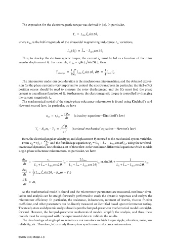
                         The mathematical model of the single-phase reluctance micromotor is found using Kirchhoff’s and
                       Newton’s second laws. In particular, we have

                                       u as =  r s i as +  dy as  (circuitry equation—Kirchhoff’s law)
                                                 ----------
                                                  dt
                                                 2
                                                d q r
                                T e –  B m w r – T L =  J----------  (torsional-mechanical equation—Newton’s law)
                                                   2
                                                 dt
                         Here, the electrical angular velocity ω r  and displacement θ r  are used as the mechanical system variables.
                                      dy as
                         From u as  = r s i as  + ----------   and the flux linkage equation ψ as  = (L ls  + L m  − L ∆m  cos2θ r ) as , using the torsional-
                                      dt
                       mechanical dynamics, one obtains a set of three first-order nonlinear differential equations which models
                       single-phase reluctance micromotors. In particular, we have
                                                                                        1
                         -------- =  – --------------------------------------------------i as –  --------------------------------------------------i as w r sin 2q r +  --------------------------------------------------u as
                                                           2L ∆m
                                        r s
                         di as
                         dt     L ls +  L m –  L ∆m cos  2q r  L ls +  L m –  L ∆m cos  2q r  L ls +  L m –  L ∆m cos  2q r
                               -- L ∆m i as sin(
                         --------- =  1  2  2q r –  B m w r – T L )
                         dw r
                         dt    J
                         -------- =  w r
                         dq r
                         dt
                         As the mathematical model is found and the micromotor parameters are measured, nonlinear simu-
                       lation and analysis can be straightforwardly performed to study the dynamic responses and analyze the
                       micromotor efficiency. In particular, the resistance, inductances, moment of inertia, viscous friction
                       coefficient, and other parameters can be directly measured or identified based upon micromotor testing.
                       The steady-state and dynamic analysis based upon the lumped-parameter mathematical model is straight-
                       forward. However, the lumped-parameter mathematical models simplify the analysis, and thus, these
                       models must be compared with the experimental data to validate the results.
                         The disadvantage of single-phase reluctance micromotors are high torque ripple, vibration, noise, low
                       reliability, etc. Therefore, let us study three-phase synchronous reluctance micromotors.


                       ©2002 CRC Press LLC

