
Page 642 - The Mechatronics Handbook
P. 642
0066_Frame_C20.fm Page 112 Wednesday, January 9, 2002 1:46 PM
Nickel Composition, Ni [%] 70 30 Iron Composition, Fe [%]
60
40
80
20
90
0 10 20 10 30
mA
Current Density,
cm 2
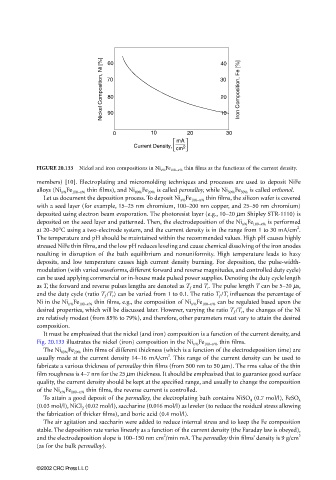
FIGURE 20.133 Nickel and iron compositions in Ni x% Fe 100−x% thin films as the functions of the current density.
members) [10]. Electroplating and micromolding techniques and processes are used to deposit NiFe
alloys (Ni x% Fe 100−x% thin films), and Ni 80% Fe 20% is called permalloy, while Ni 50% Fe 50% is called orthonol.
Let us document the deposition process. To deposit Ni x% Fe 100−x% thin films, the silicon wafer is covered
with a seed layer (for example, 15–25 nm chromium, 100–200 nm copper, and 25–50 nm chromium)
deposited using electron beam evaporation. The photoresist layer (e.g., 10–20 µm Shipley STR-1110) is
deposited on the seed layer and patterned. Then, the electrodeposition of the Ni x% Fe 100−x% is performed
2
at 20–30°C using a two-electrode system, and the current density is in the range from 1 to 30 mA/cm .
The temperature and pH should be maintained within the recommended values. High pH causes highly
stressed NiFe thin films, and the low pH reduces leveling and cause chemical dissolving of the iron anodes
resulting in disruption of the bath equilibrium and nonuniformity. High temperature leads to hazy
deposits, and low temperature causes high current density burning. For deposition, the pulse-width-
modulation (with varied waveforms, different forward and reverse magnitudes, and controlled duty cycle)
can be used applying commercial or in-house made pulsed power supplies. Denoting the duty cycle length
as T, the forward and reverse pulses lengths are denoted as T f and T r . The pulse length T can be 5–20 µs,
and the duty cycle (ratio T f /T r ) can be varied from 1 to 0.1. The ratio T f /T r influences the percentage of
Ni in the Ni x% Fe 100−x% thin films, e.g., the composition of Ni x% Fe 100−x% can be regulated based upon the
desired properties, which will be discussed later. However, varying the ratio T f /T r , the changes of the Ni
are relatively modest (from 85% to 79%), and therefore, other parameters must vary to attain the desired
composition.
It must be emphasized that the nickel (and iron) composition is a function of the current density, and
Fig. 20.133 illustrates the nickel (iron) composition in the Ni x% Fe 100−x% thin films.
The Ni 80% Fe 20% thin films of different thickness (which is a function of the electrodeposition time) are
2
usually made at the current density 14–16 mA/cm . This range of the current density can be used to
fabricate a various thickness of permalloy thin films (from 500 nm to 50 µm). The rms value of the thin
film roughness is 4–7 nm for the 25 µm thickness. It should be emphasized that to guarantee good surface
quality, the current density should be kept at the specified range, and usually to change the composition
of the Ni x% Fe 100−x% thin films, the reverse current is controlled.
To attain a good deposit of the permalloy, the electroplating bath contains NiSO 4 (0.7 mol/l), FeSO 4
(0.03 mol/l), NiCl 2 (0.02 mol/l), saccharine (0.016 mol/l) as leveler (to reduce the residual stress allowing
the fabrication of thicker films), and boric acid (0.4 mol/l).
The air agitation and saccharin were added to reduce internal stress and to keep the Fe composition
stable. The deposition rate varies linearly as a function of the current density (the Faraday law is obeyed),
2
and the electrodeposition slope is 100–150 nm cm /min mA. The permalloy thin films’ density is 9 g/cm 3
(as for the bulk permalloy).
©2002 CRC Press LLC