
Page 646 - The Mechatronics Handbook
P. 646
0066_Frame_C20.fm Page 116 Wednesday, January 9, 2002 1:47 PM
Major Fabrication Steps
Light Beam
Epoxy Substrate (FR-x)
Mirror
Copper Cantilever Beam Permanent Magnet Copper
Sacrificial Layer
Electromagnetic Force Due
Epoxy Substrate (FR-x) Epoxy Substrate (FR-x)
to Electromagnetic Field
Planar Microcoils Planar Microcoils
Controlling ICs Mirror
Copper Cantilever Beam Permanent Magnet
Spiral Microcoils:
Top View Epoxy Substrate (FR-x)
Planar Microcoils
1. Non-deflected Beam x
Mirror l
Copper Cantilever Beam Permanent Magnet Permanent Magnet
z
y
2. Deflected Beam Mirror R
Permanent Magnet Permanent Magnet
Copper Cantilever Beam
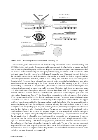
FIGURE 20.135 Electromagnetic microactuator with controlling ICs.
The electromagnetic microactuators can be made using conventional surface micromachining and
CMOS fabrication technologies through electroplating, screen printing, lamination processes, sacrificial
layer techniques, photolithography, etching, etc. In particular, the electromagnetic microactuator studied
can be made on the commercially available epoxy substrates (e.g., FR series), which have the one-sided
laminated copper layer (the copper layer thickness, which can be from 10 µm and higher, is defined by
the admissible current density and the current value needed to establish the desired magnetic field to
attain the specified mirror deflection, deflection rate, settling time, and other steady-state and dynamic
characteristics). The spiral planar microcoils can be made on the one-sides laminated copper layer using
photolithography and wet etching in the ferric chloride solution. The resulting x-µm thick N-turn
microwinding will establish the magnetic field (the number of turns is a function of the footprint area
available, thickness, spacing, outer-inner radii, geometry, fabrication techniques and processes used,
etc.). After fabrication of the planar microcoils, the cantilever beam with the permanent magnet and
mirror is fabricated on other side of the substrate. First, a photoresist sacrificial layer is spin-coated and
patterned on the substrate. Then, a Ti–Cu–Cr seed layer is deposited to perform the copper electroplating
(if the copper is used to fabricate the flexible cantilever structure). The second photoresist layer is spun
and patterned to serve as a mold for the electroplating of the copper-based cantilever beam. The copper
cantilever beam is electroplated in the copper-sulfate-based plating bath. After the electroplating, the
photoresist plating mold and the seed layer are removed releasing the cantilever beam structure. It must
be emphasized that depending upon the permanent magnet used, the corresponding fabricated processes
must be done before or after releasing the beam. The permanent-magnet disk is positioned on the
cantilever beam free end (for example, the polymer magnet can be screen-printed, and after curing the
epoxy magnet, the magnet is magnetized by the external magnetic field). Then, the cantilever beam with
the fabricated mirror is released by removing the sacrificial photoresist layer using acetone. It must be
emphasized that the studied electromagnetic microactuator is fabricated using low-cost (affordable),
high-yield micromachining—CMOS technology, processes, and materials. The most attractive feature is
the application of the planar microcoils, which can be easily made. The use of the polymer permanent
magnets (which have good magnetic properties) allows one to design high-performance electromagnetic
microactuators. It must be emphasized that the polysilicon can be used to fabricate the cantilever beam
and other permanent magnets can be applied.
©2002 CRC Press LLC