Page 651 - The Mechatronics Handbook
P. 651
0066_Frame_C20.fm Page 121 Wednesday, January 9, 2002 1:47 PM
Electromagnetic System Modeling in Microactuators with Permanent
Magnets: High-Fidelity Modeling and Analysis
In this section we focus our efforts to derive the expanded equations for the electromagnetic torque and
force on cylindrical permanent-magnet thin films, see Fig. 20.135. The permanent-magnet thin film is
assumed to be uniformly magnetized and the equations are developed for two orientations of the mag-
netization vector (the orientation is parallel to the axis of symmetry, and the orientation is perpendicular
to this axis). Electromagnetic fields and gradients produced by the planar windings should be found at a
point in inertial space, which coincides with the origin of the permanent-magnet axis system in its initial
alignment. Our ultimate goal is to control microactuators, and thus, high-fidelity mathematical models
(which will result in viable analysis, control, and optimization) must be derived. To attain our objective,
the complete equations for the electromagnetic torque and force on a cylindrical permanent-magnet thin
films are found.
The following notations are used: A, R, and l are the area, radius, and length of the cylindrical permanent
magnet; B is the magnetic flux density vector; B e is the expanded magnetic flux density vector; [∂ B] is
the matrix of field gradients [T/m]; [∂ B e ] is the matrix of expanded field gradients [T/m]; F and T are
the total force and torque vectors on the permanent-magnet thin film; i is the current in the planar
2
microwinding; m is the magnetic moment vector [A m ]; M is the magnetization vector [A/m]; r is the
position vector (x, y, z are the coordinates in the Cartesian system),
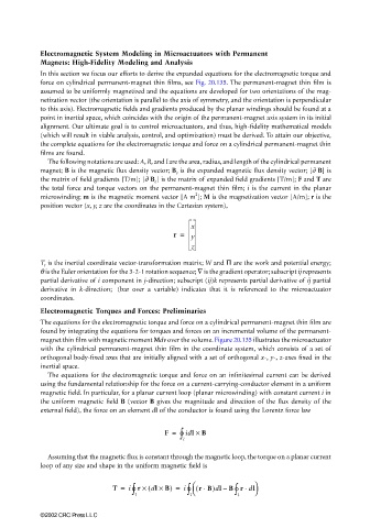
x
r = y
z
T r is the inertial coordinate vector-transformation matrix; W and Π are the work and potential energy;
θ is the Euler orientation for the 3-2-1 rotation sequence; ∇ is the gradient operator; subscript ij represents
partial derivative of i component in j-direction; subscript (ij)k represents partial derivative of ij partial
–
derivative in k-direction; (bar over a variable) indicates that it is referenced to the microactuator
coordinates.
Electromagnetic Torques and Forces: Preliminaries
The equations for the electromagnetic torque and force on a cylindrical permanent-magnet thin film are
found by integrating the equations for torques and forces on an incremental volume of the permanent-
magnet thin film with magnetic moment Mdv over the volume. Figure 20.135 illustrates the microactuator
with the cylindrical permanent-magnet thin film in the coordinate system, which consists of a set of
orthogonal body-fixed axes that are initially aligned with a set of orthogonal x-, y-, z-axes fixed in the
inertial space.
The equations for the electromagnetic torque and force on an infinitesimal current can be derived
using the fundamental relationship for the force on a current-carrying-conductor element in a uniform
magnetic field. In particular, for a planar current loop (planar microwinding) with constant current i in
the uniform magnetic field B (vector B gives the magnitude and direction of the flux density of the
external field), the force on an element dl of the conductor is found using the Lorentz force law
∫ idl ×
F = l ° B
Assuming that the magnetic flux is constant through the magnetic loop, the torque on a planar current
loop of any size and shape in the uniform magnetic field is
∫
∫
l °
⋅
⋅
T = i r × ( dl × B) = i l ° ∫ ( rB)dlB r dl
l °
–
©2002 CRC Press LLC

