
Page 648 - The Mechatronics Handbook
P. 648
0066_Frame_C20.fm Page 118 Wednesday, January 9, 2002 1:47 PM
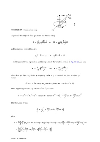
z P(x,y,z) H r
a z r r 1
a
O
r 2 y
f
i
FIGURE 20.137 Planar current loop. x
In general, the magnetic field quantities are derived using
1
∫
∫
B = 4p ° l dl × 2 r 0 or H = 4p ° l dl × 2 r 0
m 0
------i ---------------
------i ---------------
r
r
and the Ampere circuital law gives
∫ l ° H dl = i total or ∫ l ° H dl = Ni
⋅
⋅
Making use of these expressions and taking note of the variables defined in Fig. 20.137, we have
1
∫
H = 4p ° dl × 3 r 1 and B = m 0 ∫ dl × 3 r 1
4p °
------i ---------------
------i ---------------
l
r 1 l r 1
where dI = a φ a dφ = (−a x sinφ + a y cosφ)a dφ and r 1 = a x (x − acosφ) + a y (y − asinφ) + a z z.
Hence,
(
dI × r 1 = [ a x zcos f + a y zsin f a z ysin f + xcos f a)]a df.
–
–
2 2
Then, neglecting the small quantities (a << r ), we have
3
r 1 = ( x + y + z + a – 2axcos f 2aysin f) 3/2 ≈ r 1 – 2ax f – 2ay f 3/2
2
2
3
2
2
---------sin
---------cos
–
r 2 r 2
Therefore, one obtains
1 1 3ax 3ay
---- = ---- 1 + ---------cos f + ---------sin f
3
3 2 2
r 1 r r r
Thus,
1
B = m 0 a ∫ 2p [ a x zcos f + a y zsin f a z ysin f + xcos f a)]a---- 1 + 3ax f + 3ay f df
(
---------cos
--------i
---------sin
–
–
3
4p 0 r r 2 r 2
m 0 a 2 3xz 3yz 3x 2 3y 2
= -----------i a x -------- + a y -------- – a z -------- + ------- – 2
4pr 3 r 2 r 2 r 2 r 2
©2002 CRC Press LLC