
Page 608 - The Mechatronics Handbook
P. 608
0066_Frame_C20 Page 78 Wednesday, January 9, 2002 5:49 PM
Modeling of a Hydraulic Servosystem for Position Control
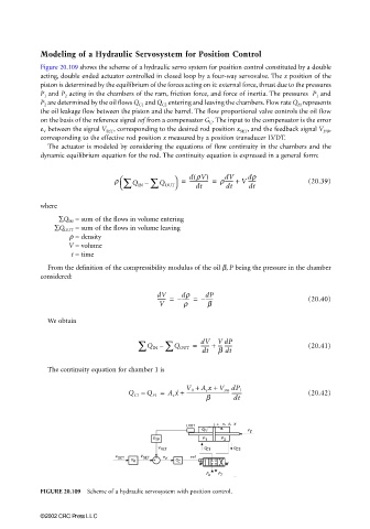
Figure 20.109 shows the scheme of a hydraulic servo system for position control constituted by a double
acting, double ended actuator controlled in closed loop by a four-way servovalve. The x position of the
piston is determined by the equilibrium of the forces acting on it: external force, thrust due to the pressures
P 1 and P 2 acting in the chambers of the ram, friction force, and force of inertia. The pressures P 1 and
P 2 are determined by the oil flows Q C1 and Q C2 entering and leaving the chambers. Flow rate Q FI represents
the oil leakage flow between the piston and the barrel. The flow proportional valve controls the oil flow
on the basis of the reference signal ref from a compensator G C . The input to the compensator is the error
e V between the signal V SET , corresponding to the desired rod position x SET , and the feedback signal V F/B ,
corresponding to the effective rod position x measured by a position transducer LVDT.
The actuator is modeled by considering the equations of flow continuity in the chambers and the
dynamic equilibrium equation for the rod. The continuity equation is expressed in a general form:
(
dr
dV
r ∑ Q IN ∑ = d rV) r------- + V ------ (20.39)
--------------- =
– Q OUT dt dt dt
where
∑Q IN = sum of the flows in volume entering
∑Q OUT = sum of the flows in volume leaving
ρ = density
V = volume
t = time
From the definition of the compressibility modulus of the oil β, P being the pressure in the chamber
considered:
dV dr dP
------- = – ------ = – ------ (20.40)
V r b
We obtain
∑ Q IN ∑ Q OUT = dV V dP (20.41)
------- +
--- ------
–
dt β dt
The continuity equation for chamber 1 is
V 0 + A c x + V sm dP 1
+
Q C1 – Q FI = A c x ˙ ----------------------------------- -------- (20.42)
b dt
FIGURE 20.109 Scheme of a hydraulic servosystem with position control.
©2002 CRC Press LLC