
Page 605 - The Mechatronics Handbook
P. 605
0066_Frame_C20 Page 75 Wednesday, January 9, 2002 5:49 PM
FIGURE 20.102 Nozzle-flapper servovalve (Moog).
x a
x j
x s
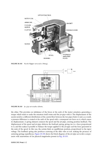
FIGURE 20.103 Jet-pipe servovalve scheme.
the other. This provokes an imbalance of the forces at the ends of the motor armature, generating a
torque which tends to make the armature itself rotate and the jet-pipe with it. The displacement of the
nozzle involves a different distribution of the control flow between the two pipes below it and, as a result,
a pressure difference is created at the ends of the spool with a consequent net force on it, which causes
its displacement. A spring element connects the spool and the jet-pipe, creating position feedback. The
displacement of the spool and jet-pipe deforms the feedback spring, giving rise to a force proportional
to it, and this makes it possible to balance the torque applied to the jet-pipe and the force generated at
the ends of the spool. In this way, the system finds an equilibrium position, proportional to the input
voltage. The feedback spring also produces centering of the slide valve at rest, making the presence of
centering springs superfluous. Figure 20.104 shows the block diagram of the jet-pipe servovalve compo-
nents with annotations of the physical magnitudes present in Fig. 20.103.
©2002 CRC Press LLC