
Page 602 - The Mechatronics Handbook
P. 602
0066_Frame_C20 Page 72 Wednesday, January 9, 2002 5:49 PM
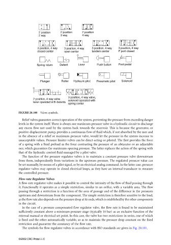
FIGURE 20.100 Valves symbols.
Relief valves guarantee correct operation of the system, preventing the pressure from exceeding danger
levels in the system itself. There is always one maximum pressure valve in a hydraulic circuit to discharge
any excess flow not used by the system back towards the reservoir. This is because the generator, or
positive-displacement pump, provides a continuous flow of fluid which, if not absorbed by the user and
in the absence of a relief or maximum pressure valve, would let the pressure in the system increase to
unacceptable values. Pressure limiter valves can be direct-acting or piloted. The first provides the force
of a spring with a fixed preload as the force contrasting the pressure of an obturator or an adjustable
one, which guarantees the maximum opening pressure. The latter replaces the action of the spring with
that of the hydraulic control fluid managed by a pilot valve.
The function of the pressure regulator valves is to maintain a constant pressure valve downstream
from them, independently from variations in the upstream pressure. The regulated pressure value can
be set manually, by means of a pilot signal, or by an electrical analog command. In the latter case, pressure
regulator valves may operate in closed electrical loops, as they have an internal transducer to measure
the controlled pressure.
Flow-rate Regulator Valves
A flow-rate regulator valve makes it possible to control the intensity of the flow of fluid passing through
it. Functionally it operates as a simple restriction, similar to an orifice, with a variable area. The flow
passing through a restriction is a function of the area of passage and of the difference in the pressures
upstream and downstream from the component. The simple restriction is therefore sensitive to the load,
as the flow rate also depends on the pressure drop at its ends, which is established by the other components
in the circuit.
In the case of a pressure-compensated flow regulator valve, the flow rate is found to be maintained
sufficiently constant above a minimum pressure stage (typically 10 bar) as an exclusive function of the
external manual or electrical set-point. In this case, the valve has two restrictions in series, one of which
is fixed and the other automatically variable, so as to maintain the pressure drop constant on the fixed
restriction and guarantee the constancy of the flow rate.
The symbols for flow regulator valves in accordance with ISO standards are given in Fig. 20.101.
©2002 CRC Press LLC