
Page 814 - The Mechatronics Handbook
P. 814
0066_Frame_C25 Page 13 Wednesday, January 9, 2002 7:05 PM
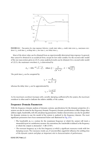
FIGURE 25.5 Parameters for step-response behavior: steady state value y s , steady state error y se , maximum over-
shoot A m , peak time t p , settling time t s , rise time t r , and delay time t d .
Most of the above value can be obtained from an experimentally determined step response. In general,
they cannot be obtained in an analytical form, except for low order models. For the second order model
of the one mass system given in (25.3), some analytical results can be obtained. For a second order model
of (25.3), the maximum overshoot A m is determined by
A
A m = 100e – pb / 1 x , where x = ----------------------, A = ln 100
2
--------
–
p + A 2 A m
2
The peak time t p can be computed by
p
t p = ------------------------
–
w n 1 x 2
whereas the delay time t d can be approximated by
1 + 0.7x
t d ≈ -------------------
w n
As the maximum overshoot increases with a smaller damping coefficient β in the system, the maximum
overshoot is often used to indicate the relative stability of the system.
Frequency Domain Parameters
With the frequency domain analysis of dynamic systems, specifications for the dynamic properties of a
system can also be stated in the frequency domain. Frequency domain specifications in filter design often
address ripple, bandwidth, roll-off, and phase lag parameters. Similar characteristics can also be specified
for dynamic systems in case the model of the system is analyzed in the frequency domain. The most
significant parameters have been summarized below and illustrated in Fig. 25.6.
• The bandwidth ω b is a notion for the maximum frequency at which the output will track a
sinusoidal input in a satisfactory manner. By convention, the bandwidth is defined as the frequency
at which the output is attenuated −3 dB (0.707).
• The resonant frequency ω r is the first frequency at which a significant resonance mode with low
damping occurs. The resonance mode can, if uncontrolled, negatively influence the settling time
of the dynamic system and plays an important role in characterization of performance.
©2002 CRC Press LLC