Page 859 - The Mechatronics Handbook
P. 859

0066_frame_C27  Page 20  Friday, January 18, 2002  5:45 PM


                         The phase margin occurs at the gain crossover frequency ω c  when |G(jω c )| = 1, or

                                                            2
                                                     ------------------------------------------- =  1
                                                           ω n
                                                                2 1/2
                                                       (
                                                     ω c ω c + 4ς ω n )
                                                         2
                                                              2
                       This equation can be rewritten as
                                                     2 2
                                                  ( ω c ) +  4ς ω n ω c ) ω n =  0
                                                           2
                                                             2
                                                                2
                                                                     4
                                                              (
                                                                  –
                       Solving for positive ω c , we obtain
                                                      2
                                                     ------ =  ( 4ς + 1) 1/2  –  2ς 2
                                                             4
                                                     ω c
                                                      2
                                                     ω n
                       Substituting s = jω c  into Eq. (27.15), the phase margin for the system is
                                            PM =  180° +  ∠ Gjω c )
                                                           (
                                                                   ω c 
                                                =  180° 90° tan  – 1   ------------ 
                                                           –
                                                      –
                                                                  2ςω n
                                                          1 1
                                                                            2 1/2
                                                =  90° tan –   ----- 4ς +([  4  1)  1/2  –  2ς ]      
                                                     –
                                                            2ς
                                                                        1/2 
                                                                1
                                                =  tan  2ς -----------------------------------------    (27.16)
                                                     1
                                                     –
                                                         ( 4ς +  1)  1/2  –  2ς 2  
                                                             4
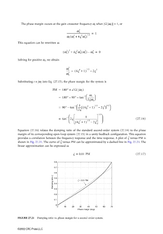
                       Equation (27.16) relates the damping ratio of the standard second-order system (27.14) to the phase
                       margin of its corresponding open-loop system (27.15) in a unity feedback configuration. This equation
                       provides a correlation between the frequency response and the time response. A plot of ζ versus PM is
                       shown in Fig. 27.21. The curve of ζ versus PM can be approximated by a dashed line in Fig. 27.21. The
                       linear approximation can be expressed as
                                                         ς =  0.01 PM                           (27.17)
                                             0.8
                                             0.7
                                             0.6
                                            Damping ratio z  0.5  z = 0.01 PM

                                             0.4
                                             0.3
                                             0.2
                                             0.1
                                              0
                                               0   10   20   30   40   50  60   70
                                                            Phase margin (deg)

                       FIGURE 27.21  Damping ratio vs. phase margin for a second-order system.


                       ©2002 CRC Press LLC
   854   855   856   857   858   859   860   861   862   863   864