
Page 858 - The Mechatronics Handbook
P. 858
0066_frame_C27 Page 19 Friday, January 18, 2002 5:45 PM
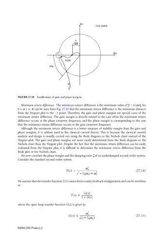
FIGURE 27.20 Insufficiency of gain and phase margins.
Minimum return difference: The minimum return difference is the minimum value of |1 + L(jω)|, for
0 < ω < ∞. It can be seen from Fig. 27.20 that the minimum return difference is the minimum distance
from the Nyquist plot to the −1 point. Therefore, the gain and phase margins are special cases of the
minimum return difference. The gain margin is directly related to the case when the minimum return
difference occurs at the phase crossover frequency, and the phase margin is corresponding to the case
that the minimum return difference occurs at the gain crossover frequency.
Although the minimum return difference is a better measure of stability margin than the gain and
phase margins, it is seldom used in the classical control theory. This is because the classical control
analysis and design is usually carried out using the Bode diagram or the Nichols chart instead of the
Nyquist plot. The gain and phase margins are more easily determined from the Bode diagram or the
Nichols chart than the Nyquist plot. Despite the fact that the minimum return difference can be easily
evaluated from the Nyquist plot, it is difficult to determine the minimum return difference from the
Bode plot or the Nichols chart.
We now correlate the phase margin and the damping ratio ζ of an underdamped second-order system.
Consider the standard second-order system
2
Ts() = ------------------------------------- (27.14)
ω n
2
s + 2ςω n s + ω n 2
We assume that the transfer function T(s) comes from a unity feedback configuration and can be rewritten
as
Gs()
Ts() = --------------------
1 + Gs()
where the open-loop transfer function G(s) is given by
2
Gs() = --------------------------- (27.15)
ω n
(
ss + 2ςω n )
©2002 CRC Press LLC