
Page 857 - The Mechatronics Handbook
P. 857
0066_frame_C27 Page 18 Friday, January 18, 2002 5:45 PM
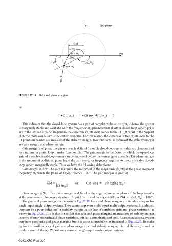
FIGURE 27.19 Gain and phase margins.
or
(
1 + Ljω cr ) = 1 + Gjω cr )Hjω cr ) = 0
(
(
This indicates that the closed-loop system has a pair of complex poles at s = ±jω cr . Hence, the system
is marginally stable and oscillates with the frequency ω cr , provided that all other closed-loop system poles
are in the left half s-plane. In general, the closer the L(jω) locus comes to the −1 + j0 point in the Nyquist
plot, the more oscillatory is the system response. For this reason, the closeness of the L(jω) locus to the
−1 point can be used as a measure of the stability margin. Two traditional measures of the stability margin
are gain margin and phase margin.
Gain margin and phase margin are usually defined for stable closed-loop systems that are characterized
by a minimum phase, loop transfer function L(s). The gain margin is the factor by which the open-loop
gain of a stable closed-loop system can be increased before the system goes unstable. The phase margin
is the amount of additional phase lag at the gain crossover frequency required to make the stable closed-
loop system marginally stable. Thus we have the following definitions:
Gain margin (GM): The gain margin is the reciprocal of the magnitude |L(jω)| at the phase crossover
frequency ω φ , where the phase of L(jω φ ) reaches −180°. The gain margin is given by
1
GM = -------------------- or GM dB) = – 20 log Ljω φ )
(
(
(
Ljω φ )
Phase margin (PM): The phase margin is defined as the angle between the phase of the loop transfer
at the gain crossover frequency ω g where L( jω ) = 1 and the angle −180°, or PM = ∠ L(jω g ) + 180° .
g
The gain and phase margins are shown in Fig. 27.19. Gain and phase margins are stability margins for
single-input single-output systems. They cannot apply for multi-input multi-output systems. In addition,
they can be a poor indication of stability margin in the face of combined gain and phase variations, as
shown in Fig. 27.20. This is due to the fact that gain and phase margins are measures of stability margin
in terms of only pure gain and phase variations, but not a combination of both. As a consequence, a system
may have good gain and phase margins, but it is close to instability, as indicated in Fig. 27.20. To make
up for the insufficiencies of gain and phase margins, a third stability margin, return difference, is used in
modern control theory. We will only consider single-input single-output systems.
©2002 CRC Press LLC