
Page 891 - The Mechatronics Handbook
P. 891
0066_Frame_C30 Page 2 Thursday, January 10, 2002 4:43 PM
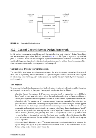
FIGURE 30.1 Generalized feedback system.
30.2 General Control System Design Framework
In this section, we present a general framework for control system (and estimator) design. Toward this
end, we consider the generalized feedback system in Fig. 30.1. In this figure, G represents a generalized
plant. G contains a model for the actual plant P (physical system) to be controlled. It may also contain
additional (frequency dependent) weighting functions that are used to address closed loop design objec-
tives. K represents a controller or compensator to be designed.
Central Idea: Design Via Optimization
The central idea here is that many important problems that arise in controls, estimation, filtering, and
other areas of engineering may be cast in terms of a generalized plant G and a controller K to be designed
2
by minimizing some norm (e.g., H ) on the closed loop transfer function matrix T wz from the signals w
to the signals z.
The Signals
To appreciate the flexibility of our generalized feedback system structure, it suffices to consider the nature
of the signals z, u, w, and y in the figure. These signals may be described as follows:
• Regulated Signals. The signals z ∈ R n z represent regulated signals or signals that we would like to
keep “small” in some sense, which depends on the application and desired performance objectives.
Such signals might include tracking errors, actuator or control inputs, signal estimation errors, etc.
• Control Signals. The signals u ∈ R n u represent control signals or manipulated variables that are
generated by the controller K. Control signals might include fuel flow to an engine, voltage applied
to a dc motor, etc. They might also include state estimates provided by K. The idea is for K to
manipulate and coordinate control signals u in a manner which keeps the regulated signals z “small.”
In practice, we typically have more signals that require “regulation” than controls (i.e., n z ≥ n u ). It
should be noted, however, that generally if we want to independently control m quantities, then
we need at least m independent controls. This basic tenet must be adhered to in practice. The
more independent controls u that are available, the easier (in principle) it is to influence the signals
z to be regulated.
• Exogenous Signals. The signals w ∈ R n w represent exogenous (or external) signals that act upon the
system. Exogenous signals may include reference commands issued to the control system, distur-
bances acting on the system, sensor noise, etc.
©2002 CRC Press LLC