Page 920 - The Mechatronics Handbook
P. 920
0066_Frame_C30 Page 31 Thursday, January 10, 2002 4:44 PM
• If the plant P = [A, B, C] is minimum phase, then it can be shown that
lim Y = 0 (30.179)
m→ 0 +
lim mH f = BV (30.180)
m→ 0 +
T
T
for some orthonormal V (i.e., V V = VV = I)
lim K opt P = L i (30.181)
m→ 0+
In such a case, K opt P ≈ L i for small m and hence K opt P will possess stability margins that are
close to those of L i (at the plant input)—whatever method was used to design L i .
It must be noted that the minimum phase condition on the plant P is a suficient condition.
It is not necessary. Moreover, H f need not be computed using a FARE. In fact, any H f which
(1) satisfies a limiting condition lim mH f = BV for some invertible matrix V and which
m → 0 +
(2) ensures that A − H f C is stable (for small m), will result in LTR at the plant input; i.e.,
lim K opt P = L i . This result is a consequence of the structure of model-based compensators
m → 0 +
and has nothing to do with optimal control and filtering problems.
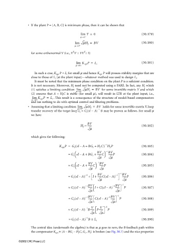
• Assuming that a limiting condition lim mH f = BV holds for some invertible matrix V, loop
m→ 0 + −1
transfer recovery of the target loop L i = G c (sI − A) B may be proven as follows. For small m
we have
H f ≈ BV (30.182)
-------
m
which gives the following:
−1
K opt P = G c sI A + BG c + H f C) H f P (30.183)
(
–
≈ G c sI A + BG c + BV −1 BV (30.184)
–
-------P
-------C
m
m
≈ G c sI A + BV −1 BV (30.185)
-------C
–
-------P
m
m
(
-------CsI A–(
≈ G c sI A) + I + BV ) −1 −1 BV (30.186)
−1
–
-------P
m m
−1BV
−1BV
≈ G c sI A) ------- I + C sI A) ------- −1 P (30.187)
(
(
–
–
m m
−1BV
−1BV
(
≈ G c sI A) ------- CsI A–( ) ------- −1 P (30.188)
–
m m
V
V
(
≈ G c sI A) B------- P------- −1 P (30.189)
−1
–
m m
(
≈ G c sI A) B = L i (30.190)
−1
–
The central idea (underneath the algebra) is that as µ goes to zero, the B feedback path within
the compensator K opt = [A − BG c − H f C, G c , H f ] is broken (see Fig. 30.7) and the nice properties
©2002 CRC Press LLC

