
Page 122 - Theory and Design of Air Cushion Craft
P. 122
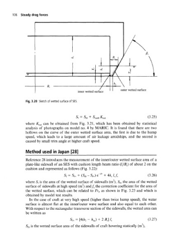
106  Steady drag forces


                                                                  outer wetted surface
                                          inner wetted surface

              Fig.  3.20  Sketch of wetted surface of  SES.


                                              o  I  o  js                        /"2  TC\
                                          f  ^iO  '  ^outO  -*^out               \J.£J)
              where  K out  can  be  obtained  from  Fig.  3.21,  which  has  been  obtained  by  statistical
              analysis  of  photographs  on  model  no.  4 by MARIC.  It  is  found  that  there  are  two
              hollows  on  the  curve  of  the  outer  wetted  surface area,  the  first  is due  to  the  hump
              speed,  which  leads  to  a  large  amount  of  air  leakage  amidships,  and  the  second  is
              caused  by small trim angle at higher craft  speed.

              Method   used  in Japan [28]

              Reference  28 introduces  the measurement  of  the inner/outer wetted surface area of  a
              plate-like sidewall of  an  SES with cushion  length beam ratio  (IJB C)  of  about  2 on  the
              cushion  and  represented  as follows  (Fig. 3.22):
                                                       Fr
                                  S  =  S  +  (S  — S~) e~  + 4h  I  f           (3.26)
              where S f is the  area  of  the wetted surface of  sidewalls (m ),  S f30 the  area  of  the wetted
                                             2
              surface  of  sidewalls at high speed  (m ) and/ s the correction  coefficient  for the  area  of
              the  wetted  surface,  which  can  be  related  to  Fr,,  as  shown  in  Fig.  3.23  and  which is
              obtained by model  test results.
                In  the  case  of  craft  at  very high  speed  (higher than  twice hump  speed),  the  water
              surface  is almost  flat  at  the  inner/outer  wave surface  and  also  equal  to  each  other.
              With respect to the rectangular transverse section of the sidewalls, the wetted area can
              be written  as
                                      S*. =  [4(A 2  -  A eq)  + 2 B,]  /,       (3.27)

              S m is the wetted surface area  of  the  sidewalls of  craft hovering statically (m ),