
Page 133 - Theory and Design of Air Cushion Craft
P. 133
Total ACV and SES drag over water 117
area of the sea-water inlet (m), C 0 the drag coefficient due to sea-water strainers, and
v the craft speed (m/s).
There are a number of methods for predicting the appendage drag. In this respect,
there is no difference between the appendages of SES and planing hulls, or displace-
ment ships: the data from these can therefore be used for reference.
3,12 Total ACV and SB drag over water
Different methodologies to calculate the total drag of ACV/SES have been compiled
and compared at MARIC [27]. Three methods for ACVs and five methods for SES
may be recommended, as summarized below.
ACV
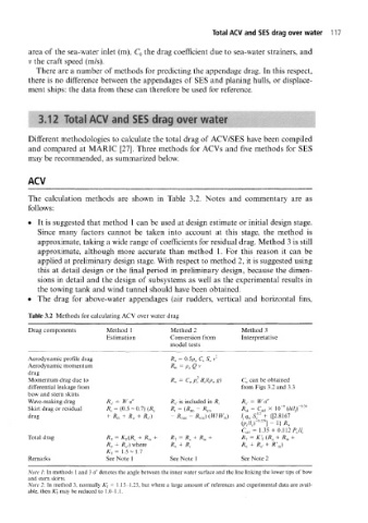
The calculation methods are shown in Table 3.2. Notes and commentary are as
follows:
• It is suggested that method 1 can be used at design estimate or initial design stage.
Since many factors cannot be taken into account at this stage, the method is
approximate, taking a wide range of coefficients for residual drag. Method 3 is still
approximate, although more accurate than method 1. For this reason it can be
applied at preliminary design stage. With respect to method 2, it is suggested using
this at detail design or the final period in preliminary design, because the dimen-
sions in detail and the design of subsystems as well as the experimental results in
the towing tank and wind tunnel should have been obtained.
• The drag for above-water appendages (air rudders, vertical and horizontal fins,
Table 3.2 Methods for calculating ACV over water drag
Drag components Method 1 Method 2 Method 3
Estimation Conversion from Interpretative
model tests
Aerodynamic profile drag
Aerodynamic momentum
drag
Momentum drag due to C w can be obtained
differential leakage from from Figs 3.2 and 3.3
bow and stern skirts
Wave-making drag /?„. = W a" R,f is included in R r R a,= Wa"
6
Skirt drag or residual R s = (0.5 ~ 0.7) (R, t R, = (R lm- R jm R A = C skl :X 10" (/i//,) °' 34
drag + R m + R v + ,,) - R mm - R wm)(W/W m) {[2.8167
R a
/J q
" C: 5 t
cl, = 1.35 + 0.112 PJl c
(1
Total drag RT = K T(R d + R m + R 7 = R a + R m + RT = K'j ^ + R m +
R n + R a.) where R-A ~^ -*^r R^. ~t~ R a» + R', k)
K T= 1.5-1.7
Remarks See Note 1 See Note 1 See Note 2
Note 1: In methods 1 and 3 a" denotes the angle between the inner water surface and the line linking the lower tips of bow
and stern skirts.
Note 2: In method 3, normally Kj = 1.15-1.25, but where a large amount of references and experimental data are avail-
able, then K'-f may be reduced to 1.0-1.1.