
Page 157 - Theory and Design of Air Cushion Craft
P. 157
140 Stability
BJB,
0.25
0.20
0.15
0.10
0.05
1 CIB C
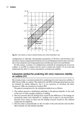
Fig. 4.4 Craft statistics of relative sidewall thickness and cushion length/beam ratio.
configuration of sidewalls, characteristic parameters of lift fans, and bow/stern seal
clearance, one has to keep in mind that the various craft design parameters have to be sim-
ilar to that adopted in the foregoing literature and the data cannot be used blindly.
For this reason, a number of complementary methods of calculating the transverse
stability of an SES on cushion may be used to analyse the stability of the craft and
understand the effect of various parameters on transverse stability.
Calculation method for predicting SES static transverse stability
on cushion [41]
We introduce here a calculation method for predicting the static transverse stability of
SES without LSK on cushion. The method for the SES with longitudinal keel can also
be obtained by similar deduction, but it is not necessary to introduce the latter
because no LSKs are mounted on modern SES.
The general assumptions for the calculation method are as follows:
1. The cushion pressure is distributed uniformly in the plenum chamber of the craft
in the case of either upright condition or heeling.
2. One may presume that the drifting force caused by the difference of the leakage air
momentum under both sidewalls of a heeling craft is equal to the lateral hydro-
dynamic force acting on them and the heeling moment caused by this induced
couple may be neglected.
3. The fan outlet is perpendicular to the wet deck of the craft and the total fan flow
blows directly into the plenum chamber.