
Page 158 - Theory and Design of Air Cushion Craft
P. 158
Static transverse stability of SES on cushion 141
4. The gaps between the lower edge of both bow and stern seals and the base-line are
equal.
Calculation of static transverse stability for an SES without LSK
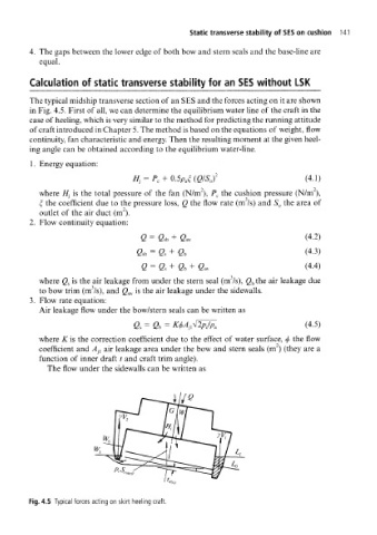
The typical midship transverse section of an SES and the forces acting on it are shown
in Fig. 4.5. First of all, we can determine the equilibrium water line of the craft in the
case of heeling, which is very similar to the method for predicting the running attitude
of craft introduced in Chapter 5. The method is based on the equations of weight, flow
continuity, fan characteristic and energy. Then the resulting moment at the given heel-
ing angle can be obtained according to the equilibrium water-line.
1. Energy equation:
(Q/S 0} 2 (4.1)
where H } is the total pressure of the fan (N/m~), P c the cushion pressure (N/nT),
£ the coefficient due to the pressure loss, Q the flow rate (m /s) and S 0 the area of
outlet of the air duct (m").
2. Flow continuity equation:
Q = &b + Qsw (4.2)
sb = Q, + Gb (4.3)
fi = e, + a, + (4.4)
where Q s is the air leakage from under the stern seal (m /s), Q b the air leakage due
to bow trim (m /s), and Q sw is the air leakage under the sidewalls.
Flow rate equation:
Air leakage flow under the bow/stern seals can be written as
fi s = fi b = (4.5)
where K is the correction coefficient due to the effect of water surface, </> the flow
coefficient and A- }1 air leakage area under the bow and stern seals (m ) (they are a
function of inner draft t and craft trim angle).
The flow under the sidewalls can be written as
Fig. 4.5 Typical forces acting on skirt heeling craft.