
Page 200 - Theory and Design of Air Cushion Craft
P. 200
Dynamic stability, plough-in and overturning 183
positive stability is practical has been greatly extended, and sensitivity to plough-in
and capsizing has been significantly reduced.
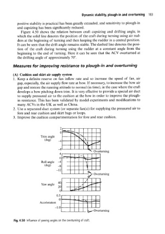
Figure 4.50 shows the relation between craft capsizing and drifting angle, in
which the solid line denotes the position of the craft during turning using air rud-
ders at the beginning of turning and then keeping the rudder in a central position.
It can be seen that the drift angle remains stable. The dashed line denotes the posi-
tion of the craft during turning using the rudder at a constant angle from the
beginning to the end of turning. Here it can be seen that the ACV overturned at
the drifting angle of approximately 70°.
Measures for improving resistance to plough-in and overturning
(A) Cushion and skirt air supply system
1. Keep a definite reserve on fan inflow rate and so increase the speed of fan, air
gap, especially, the air supply flow rate at bow. If necessary, to increase the bow air
gap and restore the running attitude to normal (in time), in the case where the craft
develops a bow pitching down trim. It is very effective to provide a special air duct
to supply pressured air to the cushion at the bow in order to improve the plough-
in resistance. This has been validated by model experiments and modifications to
many ACVs in the UK as well as China.
2. Use a separated duct system (or separate fan(s)) for supplying the pressured air to
fore and rear cushion and skirt bags or loops.
3. Improve the cushion compartmentation for fore and rear cushion.
L
0 *i^
*V
Trim angle x N,
(deg) _4 — * \ \ *s
V .4 *~
8 ft—
Overturning
^ H
0 V .— *• •^•a
Roll angle -4 \
(deg) o \
'
— 12.
<*v > Overturning
c/
/
/
v i 40 />
Yaw angle
* 20 S .* ^ *— •
0 ^ .--
0.5
0 ••••i «-s
Acceleration •— •» -^ ^
1 0
-^^- Overturning
Fig. 4.50 Influence of yawing angles on the overturning of craft.