
Page 406 - Thermal Hydraulics Aspects of Liquid Metal Cooled Nuclear Reactors
P. 406
Multi-scale simulations of liquid metal systems 369
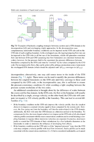
Fig. 7.3 Examples of hydraulic coupling strategies between a system and a CFD domain in the
decomposition (left) and overlapping (right) approaches. In the decomposition case,
complementary inlet/outlet boundary conditions can be imposed on the STH side and on the
CFD side of each coupling boundary. In the overlapped case, the ingoing/outgoing flow rate can
be imposed in the CFD code in all but one of the boundaries, which will guarantee consistent
flow rate between STH and CFD (assuming that flow boundaries are consistent between the
codes); however, for the pressure field to be consistent, the pressure differences between
boundaries computed by the STH code must be “overlaid” by the values computed by the CFD
code. For incompressible flows, this can be achieved by adding a momentum source term inside
the overlapped STH domain (which should be adjusted until ΔP STH converges to ΔP CFD ).
decomposition; alternatively, one may add source terms to the inside of the STH
domain (Fig. 7.3, right). These terms can be used to modify the pressure differences
between the coupled boundaries on the STH side until they converge to those used
computed by the CFD code; in the incompressible case, this is sufficient to ensure
the pressure-consistency condition (3) while avoiding a tight coupling between the
pressure system resolutions of the two codes.
An additional consideration is brought about by the difference of scales between
the coarse and the fine domain. In the STH code, the flow at the boundary will usually
be described by a single, average velocity; on the other hand, the CFD code will com-
pute (or require) a 3-D velocity profile at the boundary. This can lead to several dif-
ficulties (Fig. 7.4):
l If the boundary condition on the CFD side imposes the velocity profile, then the simplest
choice is to impose a constant velocity equal to those computed by the system code. How-
ever, the flow going out from the boundary will then be undeveloped in the CFD domain;
additionally, the flow will enter the CFD domain at a direction normal to the boundary. To
compensate for this, the most elegant solution is to impose on the CFD side a fully developed
velocity profile consistent with the mass-conservation condition and to avoid locating a cou-
pling boundary in regions where transverse velocities are expected. In practice, most users
prefer to extend the CFD domain of their calculations by a few hydraulic diameters at the
inlet/outlet in order to minimize the influence of developing flow effects.
l If the boundary condition on the CFD side is of the “imposed pressure” type, then the CFD
code may compute a velocity profile with local flow inversions. Such a profile can be made
consistent with the conservation conditions (1)–(3) but is considered undesirable, as it cannot