
Page 408 - Thermal Hydraulics Aspects of Liquid Metal Cooled Nuclear Reactors
P. 408
Multi-scale simulations of liquid metal systems 371
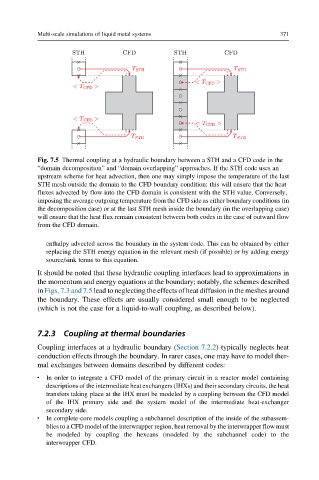
Fig. 7.5 Thermal coupling at a hydraulic boundary between a STH and a CFD code in the
“domain decomposition” and “domain overlapping” approaches. If the STH code uses an
upstream scheme for heat advection, then one may simply impose the temperature of the last
STH mesh outside the domain to the CFD boundary condition: this will ensure that the heat
fluxes advected by flow into the CFD domain is consistent with the STH value. Conversely,
imposing the average outgoing temperature from the CFD side as either boundary conditions (in
the decomposition case) or at the last STH mesh inside the boundary (in the overlapping case)
will ensure that the heat flux remain consistent between both codes in the case of outward flow
from the CFD domain.
enthalpy advected across the boundary in the system code. This can be obtained by either
replacing the STH energy equation in the relevant mesh (if possible) or by adding energy
source/sink terms to this equation.
It should be noted that these hydraulic coupling interfaces lead to approximations in
the momentum and energy equations at the boundary; notably, the schemes described
in Figs. 7.3 and 7.5 lead to neglecting the effects of heat diffusion in the meshes around
the boundary. These effects are usually considered small enough to be neglected
(which is not the case for a liquid-to-wall coupling, as described below).
7.2.3 Coupling at thermal boundaries
Coupling interfaces at a hydraulic boundary (Section 7.2.2) typically neglects heat
conduction effects through the boundary. In rarer cases, one may have to model ther-
mal exchanges between domains described by different codes:
In order to integrate a CFD model of the primary circuit in a reactor model containing
l
descriptions of the intermediate heat exchangers (IHXs) and their secondary circuits, the heat
transfers taking place at the IHX must be modeled by a coupling between the CFD model
of the IHX primary side and the system model of the intermediate heat-exchanger
secondary side.
l In complete-core models coupling a subchannel description of the inside of the subassem-
blies to a CFD model of the interwrapper region, heat removal by the interwrapper flow must
be modeled by coupling the hexcans (modeled by the subchannel code) to the
interwrapper CFD.