
Page 32 - Uninterruptible Power Supplies
P. 32
Standby Power Generating Sets
30 Chapter One
4
5 3 2 6
1
Plan
4
3
5 1 2 6
Elevation
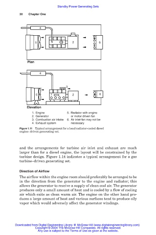
1. Engine 5. Radiator with engine
2. Generator or motor driven fan
3. Combustion air intake 6. Air inlet-fan may not be
4. Exhaust system necessary
Figure 1.11 Typical arrangement for a local radiator-cooled diesel
engine–driven generating set.
and the arrangements for turbine air inlet and exhaust are much
larger than for a diesel engine, the layout will be constrained by the
turbine design. Figure 1.14 indicates a typical arrangement for a gas
turbine–driven generating set.
Direction of Airflow
The airflow within the engine room should preferably be arranged to be
in the direction from the generator to the engine and radiator; this
allows the generator to receive a supply of clean cool air. The generator
produces only a small amount of heat and is cooled by a flow of cooling
air which exits as clean warm air. The engine on the other hand pro-
duces a large amount of heat and various surfaces tend to produce oily
vapor which would adversely affect the generator windings.
Downloaded from Digital Engineering Library @ McGraw-Hill (www.digitalengineeringlibrary.com)
Copyright © 2004 The McGraw-Hill Companies. All rights reserved.
Any use is subject to the Terms of Use as given at the website.