
Page 33 - Uninterruptible Power Supplies
P. 33
Standby Power Generating Sets
Standby Power Generating Sets 31
7 5 6
Elevation B-B
4
9 3
8
1 2
Elevation A-A
7 5 6
B B
4
9 1 3 2 8
A A
Plan
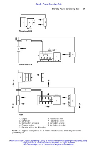
1. Engine 6. Radiator air inlet
2. Generator 7. Radiator air outlet
3. Combustion air intake 8. Ventilation air inlet
4. Exhaust system 9. Ventilation air outlet
5. Radiator with motor driven fan
Figure 1.12 Typical arrangement for a remote radiator-cooled diesel engine–driven
generating set.
Downloaded from Digital Engineering Library @ McGraw-Hill (www.digitalengineeringlibrary.com)
Copyright © 2004 The McGraw-Hill Companies. All rights reserved.
Any use is subject to the Terms of Use as given at the website.