
Page 35 - Uninterruptible Power Supplies
P. 35
Standby Power Generating Sets
Standby Power Generating Sets 33
10
5 1 2 3
A A
8 6
4
7 9
Plan
10
9
4
5
1
8 2 3
7
6
Elevation A-A
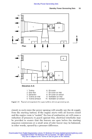
1. Turbine 6. Oil cooler
2. Gear Box 7. Oil cooler air inlet
3. Generator 8. Oil cooler air extract
4. Turbine air inlet 9. Ventilation air inlet
5. Turbine exhaust 10. Ventilation air extract
Figure 1.14 Typical arrangement for a gas turbine–driven generating set.
closed; in such cases the power opening will usually use the dc supply
from the starting battery. If the engine starts with all louvers closed
and the engine room is “sealed,” the loss of combustion air will cause a
reduction of pressure; to guard against this, electrical interlocks may
be provided to ensure that the louvers are open before the starting
sequence commences or a small area of inlet louver may be balanced,
in other words, opened by a pressure difference.
Downloaded from Digital Engineering Library @ McGraw-Hill (www.digitalengineeringlibrary.com)
Copyright © 2004 The McGraw-Hill Companies. All rights reserved.
Any use is subject to the Terms of Use as given at the website.