
Page 34 - Uninterruptible Power Supplies
P. 34
Standby Power Generating Sets
32 Chapter One
4
9 3
6
1 5 2 8
ELEVATION A-A
4
9 1 3 5 2 8
A A
6
7
PLAN
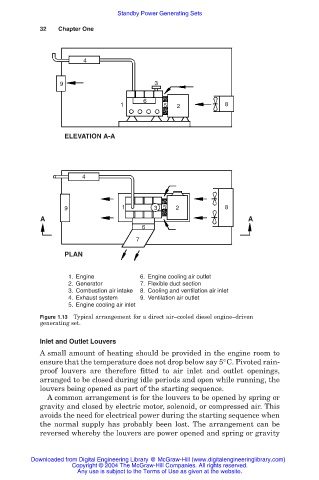
1. Engine 6. Engine cooling air outlet
2. Generator 7. Flexible duct section
3. Combustion air intake 8. Cooling and ventilation air inlet
4. Exhaust system 9. Ventilation air outlet
5. Engine cooling air inlet
Figure 1.13 Typical arrangement for a direct air–cooled diesel engine–driven
generating set.
Inlet and Outlet Louvers
A small amount of heating should be provided in the engine room to
ensure that the temperature does not drop below say 5°C. Pivoted rain-
proof louvers are therefore fitted to air inlet and outlet openings,
arranged to be closed during idle periods and open while running, the
louvers being opened as part of the starting sequence.
A common arrangement is for the louvers to be opened by spring or
gravity and closed by electric motor, solenoid, or compressed air. This
avoids the need for electrical power during the starting sequence when
the normal supply has probably been lost. The arrangement can be
reversed whereby the louvers are power opened and spring or gravity
Downloaded from Digital Engineering Library @ McGraw-Hill (www.digitalengineeringlibrary.com)
Copyright © 2004 The McGraw-Hill Companies. All rights reserved.
Any use is subject to the Terms of Use as given at the website.