
Page 63 - Using ANSYS for Finite Element Analysis A Tutorial for Engineers
P. 63
50 • Using ansys for finite element analysis
h O
h O + ∆h P
x x, u
L T 4@L = L T
(a) (b)
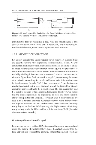
Figure 1.12. (a) A tapered bar loaded by axial force P, (b) Discretization of the
bar into four uniform two-node elements of equal length.
axisymmetric pressure vessel has a thick wall, one should regard it as a
solid of revolution, rather than a shell of revolution, and choose axisym-
metric solid elements, rather than axisymmetric shell elements.
1.9.2 discretization error
Let us now consider the axially tapered bar of Figure 1.4 in more detail
and describe how the FEM implements the mathematical model. We will
assume that a satisfactory mathematical model is based on a state of uniax-
ial stress. An analytical solution is then rather easy, but we pretend not to
know it and ask for an FE solution instead. We discretize the mathematical
model by dividing it into two node elements of constant cross-section, as
shown in Figure 1.4b. Each element has length L, accounts only for a con-
stant uniaxial stress along its length, and has an axial deformation given
by the elementary formula PL/AE. For each element, A may be taken as
constant and equal to the cross-sectional area of the tapered bar at an x
coordinate corresponding to the element center. The displacement of load
P is equal to the sum of the element deformations. Intuitively, we expect
that the exact displacement be approached as more and more elements
are used to span the total length LT. However, even if many elements are
used there is an error, known as discretization error, which exists because
the physical structure and the mathematical model each has infinitely
many degrees of freedom (DOF) (namely, the displacements of infinitely
many points), while the FE model has a finite number of DOF (the axial
displacements of its nodes).
how Many elements are enough?
Imagine that we carry out two FEAs, the second time using a more refined
mesh. The second FE model will have lesser discretization error than the
first, and will also represent the geometry better if the physical object has