
Page 62 - Using ANSYS for Finite Element Analysis A Tutorial for Engineers
P. 62
IntroductIon to FInIte element AnAlysIs • 49
A problem Anticipate A problem Preprocess
must be physical must be prepare the
solved behavior solved FE model
plan how
FE results
will be Plan revised
Is FE Yes checked to FE model
analysis using insight
required? see if they Solve
are provided by equations of
reasonable the current the FE model
FE model
Analytical or
experimental No
solution Postprocess
Are results reasonable? display FE
Yes Are error estimates small? results
Stop Does model revision do little
to alter computed results? Computer
software
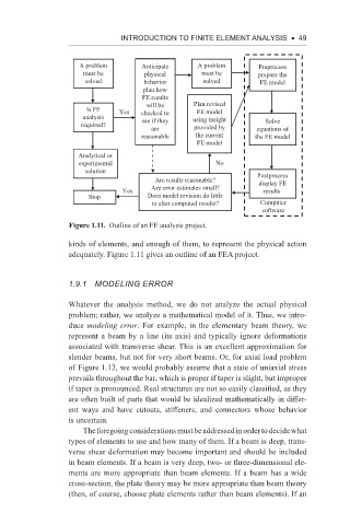
Figure 1.11. Outline of an FE analysis project.
kinds of elements, and enough of them, to represent the physical action
adequately. Figure 1.11 gives an outline of an FEA project.
1.9.1 Modeling error
Whatever the analysis method, we do not analyze the actual physical
problem; rather, we analyze a mathematical model of it. Thus, we intro-
duce modeling error. For example, in the elementary beam theory, we
represent a beam by a line (its axis) and typically ignore deformations
associated with transverse shear. This is an excellent approximation for
slender beams, but not for very short beams. Or, for axial load problem
of Figure 1.12, we would probably assume that a state of uniaxial stress
prevails throughout the bar, which is proper if taper is slight, but improper
if taper is pronounced. Real structures are not so easily classified, as they
are often built of parts that would be idealized mathematically in differ-
ent ways and have cutouts, stiffeners, and connectors whose behavior
is uncertain.
The foregoing considerations must be addressed in order to decide what
types of elements to use and how many of them. If a beam is deep, trans-
verse shear deformation may become important and should be included
in beam elements. If a beam is very deep, two- or three- dimensional ele-
ments are more appropriate than beam elements. If a beam has a wide
cross-section, the plate theory may be more appropriate than beam theory
(then, of course, choose plate elements rather than beam elements). If an