
Page 112 - Volcanic Textures A Guide To The Interpretation of Textures In Volcanic Rocks
P. 112
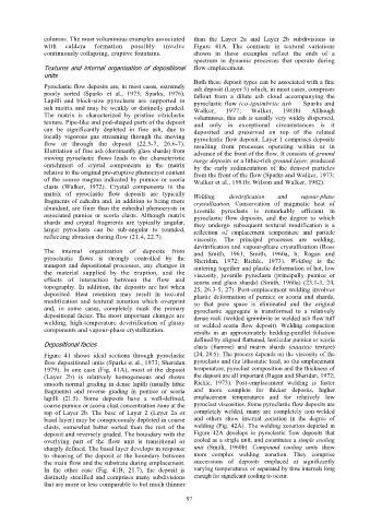
columns. The most voluminous examples associated   than the  Layer 2a and  Layer 2b subdivisions in
               with   caldera  formation   possibly   involve  Figure 41A. The contrasts in  textural variations
               continuously collapsing, eruptive fountains.    shown in these examples reflect  the  ends  of  a
                                                               spectrum in dynamic processes that operate  during
               Textures and internal organization of depositional   flow emplacement.
               units
                                                               Both these deposit types can be associated with a fine
               Pyroclastic flow deposits are, in most cases, extremely   ash deposit (Layer 3) which, in most cases, comprises
               poorly  sorted (Sparks et  al., 1973; Sparks, 1976).   fallout from  a dilute  ash cloud accompanying the
               Lapilli and block-size  pyroclasts  are  supported in   pyroclastic flow (co-ignimbrite ash — Sparks and
               ash matrix and may be weakly or distinctly graded.   Walker,  1977;  Walker,  1981b).  Although
               The matrix is characterized by  pristine vitriclastic   voluminous, this ash is usually very widely dispersed,
               texture. Pipe-like and pod-shaped parts of the deposit   and  only in  exceptional circumstances is it
               can be significantly depleted in fine ash, due to   deposited  and preserved on top of the related
               locally vigorous gas streaming through the moving   pyroclastic flow deposit. Layer 1 comprises deposits
               flow  or through the deposit (22.5-7, 26.6-7).   resulting from processes operating within or in
               Elutriation of fine ash (dominantly glass shards) from   advance of the front of the flow. It consists of ground
               moving  pyroclastic  flows  leads to the characteristic   surge deposits or a lithic-rich ground layer, produced
               enrichment of crystal components in the matrix   by the early  sedimentation of the densest particles
               relative to the original pre-eruptive phenocryst content   from the front of the flow (Sparks and Walker, 1973;
               of the source magma indicated by pumice or scoria   Walker et al., 1981b; Wilson and Walker, 1982).
               clasts (Walker, 1972).  Crystal components in the
               matrix  of  pyroclastic flow  deposits are typically   Welding,  devitrification  and  vapour-phase
               fragments of euhedra and, in addition to being more   crystallization.  Conservation of magmatic heat of
               abundant, are finer than the euhedral phenocrysts in   juvenile pyroclasts is remarkably efficient  in
               associated pumice or scoria clasts. Although  matrix   pyroclastic flow deposits, and the degree to  which
               shards and crystal fragments are typically angular,   they undergo subsequent  textural  modification is a
               larger pyroclasts can be  sub-angular to rounded,   reflection of  emplacement  temperature and particle
               reflecting abrasion during flow (21.4, 22.7).   viscosity. The principal  processes are welding,
                                                               devitrification and vapour-phase crystallisation (Ross
               The internal organization of deposits from      and Smith,  1961; Smith,  1960a, b; Ragan and
               pyroclastic  flows is  strongly controlled  by the   Sheridan, 1972; Riehle,  1973).  Welding  is the
               transport and depositional processes,  any  changes  in   sintering together and plastic deformation of hot, low
               the material supplied by the eruption, and the   viscosity, juvenile  pyroclasts (principally pumice or
               effects of  interaction between  the flow  and   scoria and  glass shards)  (Smith, 1960a)  (23.1-3, 24,
               topography. In addition, the deposits  are hot when   25, 26.3-5, 27). Post-emplacement welding involves
               deposited. Heat retention may result in  textural   plastic deformation of pumice or scoria and shards,
               modification and textural  zonation which overprint   so that pore space  is  eliminated  and  the  original
               and,  in  some  cases, completely mask the primary   pyroclastic aggregate is transformed to  a relatively
               depositional facies. The most important changes are   dense rock (welded ignimbrite or welded ash flow tuff
               welding, high-temperature  devitrification of glassy   or welded scoria flow deposit).  Welding compaction
               components and vapour-phase crystallization.    results in an  approximately bedding-parallel foliation
                                                               defined by aligned flattened, lenticular pumice or scoria
               Depositional facies                             clasts (fiamme) and matrix shards  (eutaxitic  texture)

               Figure 41 shows ideal sections through pyroclastic   (24, 28.5). The process depends on the viscosity of the
               flow depositional units (Sparks et al., 1973; Sheridan   pyroclasts and the lithostatic load, so the emplacement
               1979). In one case (Fig. 41A), most of the deposit   temperature, pyroclast composition and the thickness of
               (Layer 2b) is relatively  homogeneous  and  shows   the deposit are all important (Ragan and Sheridan, 1972;
               smooth normal grading in dense lapilli (usually lithic   Riehle,  1973). Post-emplacement welding is faster
               fragments) and  reverse  grading in  pumice or scoria   and  more  complete for thicker deposits, higher
               lapilli (21.5). Some  deposits have a well-defined,   emplacement temperatures  and  for relatively  low
               coarse pumice or scoria clast concentration zone at the   pyroclast viscosities. Some pyroclastic flow deposits are
               top  of Layer  2b. The base  of Layer 2  (Layer 2a  or   completely welded, many are completely  non-welded
               basal layer) may be conspicuously depleted in coarse   and  others show internal zonation in the degree  of
               clasts, somewhat better sorted  than the rest of the   welding (Fig. 42A). The welding zonation depicted in
               deposit and reversely graded. The boundary with the   Figure 42A develops in pyroclastic flow  deposits  that
               overlying part of the flow unit is  transitional or   cooled as a single unit, and constitutes a simple cooling
               sharply defined. The basal layer develops in response   unit  (Smith, 1960b).  Compound cooling units  show
               to shearing of the deposit at the boundary  between   more  complex  welding zonation. They comprise
               the main flow and the substrate during emplacement.   successions of  deposits  emplaced at  significantly
               In the other  case (Fig.  41B; 21.7), the deposit is   varying temperatures or separated by time intervals long
               distinctly stratified and comprises many subdivisions   enough for significant cooling to occur.
               that are more or less comparable to but much thinner

                                                             97