
Page 121 - Welding Robots Technology, System Issues, and Applications
P. 121
108 Welding Robots
during the welding process. Unfortunately, it is very difficult to control the
penetration during the welding process since there is no way to measure it on-line.
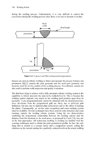
Bead
width
Bead height
penetration
leg
penetration leg
Figure 4.2. V-groove and fillet weld geometrical parameters
Sensors are used in robotic welding to detect and measure the process features and
parameters [4]-[7], namely the joint geometry and the weld pool geometry and
location, used for on-line control of the welding process. Nevertheless, sensors are
also used to perform weld inspection and quality evaluation.
The first basic thing to achieve with a fully automatic robotic welding system is the
capability to follow precisely the joint to be welded [3]-[11]. This is because the
welding quality depends very much on the welding pool position apart from its
geometry. A pre-programmed path cannot be obtained with the desired precision,
since deviations from the programmed path are likely due to deficient path
definition, but also due to material plate deficiencies and to the effect of heating
the plates. Consequently, an on-line joint recognition and seam tracking system
must be available. Several techniques have been used for joint detection and seam
tracking, namely for welding robotic systems. Using the arc characteristics
exploiting the proportional relationship between the welding current and the
distance from the electrode to the work-piece, as proposed by Cook [12], was one
of the first approaches. All technicians working in welding are familiar with the
weaving techniques used to obtain the joint geometrical profile. In fact, the only
thing that is needed is a current sensor and a comparison system: setting the
reference as the current reading for a perfectly centered torch on the actual welding