
Page 123 - Welding Robots Technology, System Issues, and Applications
P. 123
110 Welding Robots
considered, the most used approach with CCD cameras is to make a teaching pass
before the welding process is actually initiated. Theoretically this is a good
solution since a good reading of the welding seam can be recorded and used to
guide the system during the welding process. The drawbacks of this approach are
the reduction of arc-on time and the insensitivity to deviations, even if small, of the
welding seam that can happen due to the extremely high temperatures
characteristic of the welding process and deficiencies on the material of the plates
to be welded [13]-[19].
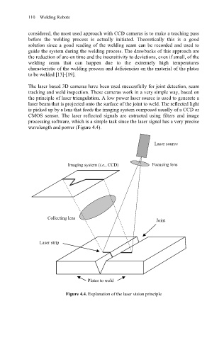
The laser based 3D cameras have been used successfully for joint detection, seam
tracking and weld inspection. These cameras work in a very simple way, based on
the principle of laser triangulation. A low power laser source is used to generate a
laser beam that is projected onto the surface of the joint to weld. The reflected light
is picked up by a lens that feeds the imaging system composed usually of a CCD or
CMOS sensor. The laser reflected signals are extracted using filters and image
processing software, which is a simple task since the laser signal has a very precise
wavelength and power (Figure 4.4).
Laser source
Imaging system (i.e., CCD) Focusing lens
Collecting lens
Joint
Laser strip
Plates to weld
Figure 4.4. Explanation of the laser vision principle