
Page 184 - Welding Robots Technology, System Issues, and Applications
P. 184
172 Welding Robots
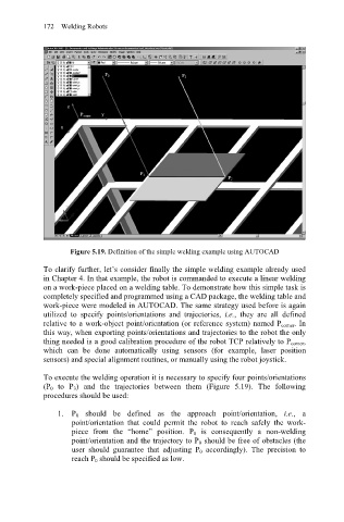
Figure 5.19. Definition of the simple welding example using AUTOCAD
To clarify further, let’s consider finally the simple welding example already used
in Chapter 4. In that example, the robot is commanded to execute a linear welding
on a work-piece placed on a welding table. To demonstrate how this simple task is
completely specified and programmed using a CAD package, the welding table and
work-piece were modeled in AUTOCAD. The same strategy used before is again
utilized to specify points/orientations and trajectories, i.e., they are all defined
relative to a work-object point/orientation (or reference system) named P corner. In
this way, when exporting points/orientations and trajectories to the robot the only
thing needed is a good calibration procedure of the robot TCP relatively to P corner,
which can be done automatically using sensors (for example, laser position
sensors) and special alignment routines, or manually using the robot joystick.
To execute the welding operation it is necessary to specify four points/orientations
(P 0 to P 3) and the trajectories between them (Figure 5.19). The following
procedures should be used:
1. P 0 should be defined as the approach point/orientation, i.e., a
point/orientation that could permit the robot to reach safely the work-
piece from the “home” position. P 0 is consequently a non-welding
point/orientation and the trajectory to P 0 should be free of obstacles (the
user should guarantee that adjusting P 0 accordingly). The precision to
reach P 0 should be specified as low.