
Page 103 - Whole Earth Geophysics An Introductory Textbook For Geologists And Geophysicists
P. 103
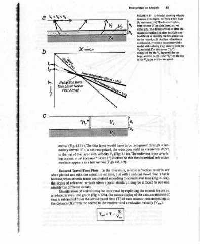
Model  showing  velocity   layer   thin  layer,  arrives   first  refraction   is   directly  over  the   layer  will  be  too   to  the  top


      85   with  depth,  but  with  a  thin   the  direct  arrival,  or  after  the  refraction  (or  after  both);  it  may   If  the  first  refraction   thickness  (“h,”)   (also  “h,”)   too  small.   sec-   a   depth   overly-   refraction   are   is   4.12a),   and   on   of   to

      Models   a)   4.11  (hy  very  small).  b)  The  first  refraction,   top  of  the   to  identify  the  overlooked,  inversion  equations  yield  a  model  with  velocity  (V,)   V,  for  the   the  depth   of  the  V,  layer  will  be   through   erroneous   layer   critical   records   travel  time. That   (Fig.   time   see   to  difficult   traces  seismic   amount  data,  an   according   trace   (V,.4):  velocity

      Interpretation   FIGURE   in   from  the   either  after   second   be  difficult   on  the  record.  c)   V; material. The   computed   large,  and   recognized   an   yield   sediment   its   that   refraction   reduced   travel   be   may   the   seismic   reduction


                                                                          to   be   equations   4.11c).  The   thin   so   seismic   a   with   actual   to   it   replotting   a display  of  the   each   a
                                                                          have   (Fig.   often   (Figs.  4.8,  4.9).   literature,   but   similar;   by   such   of   (T)   and   Xx   Vis

                                                                          would   the   V;   is   1”)   the   time,   according   appear   improved   On   time   receiver       7,   =

                                                                           layer   recognized,   velocity   arrival   In   travel   plotted   often   be   may   (Fig.  4.12b).   travel   the   to   Trea


                           =               N  My,                          thin   not   with   (oceanic  “Layer   as  a  first   Plots   actual   are   arrivals   actual   source
                         +                                                   is   it   layer   the   traces   events.   arrivals   graph   the   the
                           x               from                            4.11b).  The   if  arrival;   the   of   crust   appears   Travel-Time   with   seismic   refracted   different   of   travel-time   from   from


                                GY         Refraction  Never   Layer   First Arrival   (Fig.  arrival   ondary   top   the   oceanic   nowhere   Reduced   not   plotted   of   the   Identification   subtracted   (X)  distance

                              ‘y             Thin                              to   ing    because,  when   slopes   identify   reduced   is
                                                                                         often       time
                                           |                                                 the   a   the


          have            consists    layer   the   The   thick   is   V;   first   higher   layer   (a).   for   is   and   from   that
          land              (Fig.  4.9b).   equations   layer.   the   that   4.10b).   too   velocity   as  a   of  low-velocity   graph   observed   from   and  V,)   that  “h,”  is   absent.
          on           refraction).   thus   the   thin   a   graph   be   observed   Model   refraction   velocity  (V3).   (V,   (“t,”)  determined  the  two-layer  equations   upper  layer,  and
          exposed      Moho   crust  oceanic   interfaces   where   and   layer   critical  refraction  from   travel-time   V,   (Fig.   will   V,   layer   with   a)   4.10  layer,  sandwiched  between  velocities  (V,, V3).  No  critical  refraction  can  occur  from  the  low-velocity   b)  Travel-time   the  layer  with   that  would  result   of  velocities   time   in  text.  Note   the   low-velocity  layer  is


          sequences   ;   shallow  intrusions)   mantle;  gives   of   areas   four   from   situations   low-velocity   no   is   the   from   with   layer   the   with   layer   the   The  small).   refraction  critical   FIGURE   (V,)   (Fig.  3.23a).   only  critical   The   from   Model   ¢)   inversion   intercept   (b),  using   presented   thicker  than   the


      Interpretation   ophiolite  with   sediments   and  (volcanics   intrusions)  (deeper   (uppermost   profiles   in   and  water  refractions   common   two   are   a  results:   There   V;).   <   appear   will   It   directly   below   and   V,,   with   with   but   very   h,   the   is  nowhere


      Refraction   comparisons   water  column   deep-sea   basalt   gabbro   peridotite   of  refraction   the   There   yield  erroneous   V,   <   (V,   4.10a).   (Fig.   lies   V;   layer   no   yield   V),   that


     Seismic   and  drilling  following  stratigraphy:   =   1  Layer   =  Layer  2   Layer  3   =   4  Layer   =   appearance   through  arrival   Problem Situations   will  above   layer   velocity   V,   velocity   will   4.10c).   layer  (V;>V.,>   4.11a)   Fig.   /      L-6.   r


     Chapter4   Deep-sea   the   to   led   The general   direct   of  a   presented   1. Low-velocity   with   layer  with   equations   (Fig.   Thin   2.   thin   so   V5   <  <  V;   vs   away   ace   Int


     84                                               V,   .   Refracted   from  V,/V,
                                                      a