
Page 93 - Whole Earth Geophysics An Introductory Textbook For Geologists And Geophysicists
P. 93
75 3. arrivals to con- 1992, to example, pp. single interface. 1): yields
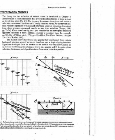
Models Chapter in of linear relate arrivals with layers determined (Burger, exactly for 1995; Geldart, a from dipping Chapter (see inversion profiles. Events plotted on travel-time.graph, (X,), and crossover distance
Interpretation developed identification through For waves. velocities velocities correspond not (see, and result would single ways and 2) refraction distance
is drawn apparent layer do necessary Sheriff that a and two in graphs; actual travel-time graph.'a) Seismic traces showing events on uninterpreted record. arrivals. c)
waves the lines refracted interfaces, true velocities is analysis of graphs interfaces, used be travel-time from arrivals, critical
seismic involves of slopes critically to exactly layer 433-439 pp. can to interpret arrivals.
of data refraction The and horizontal true dip, elaborate 1976; travel-time horizontal models anticipated of interfaces events define direct and critically refracted critically refracted model used
MODELS refraction the of seismic 4.3). (Fig. plots direct by encountered by separated inverses correspond interfaces more a al., et Telford 1990). show below interface, several the from developed gives modeling dips thicknesses, and interpretation from (t,), slopes for direct and
INTERPRETATION for theory The Interpretation travel-time on velocities velocity stant slope from Where 72-74). pp. apparent velocities; pp. of 281-284 of Fowler, 124-126 models The horizontal Equations forward 1) velocities, X= Refraction through lines drawn the T-axis intercept identified. d) Simple horizontal interface
, a iE FIGURE 4.3 b) Straight with (X,,)
material or weathered) in seismic refraction
top of the mantle
Critical refraction from the (unconsolidated (T) is commonly plotted downward =—_ be at about
Interpretation a) velocity between soft travel time the Earth. 25+ 10h = 2X In order to see a critical refraction clearly as a first arrival, the spread length should
Refraction Two problems addressed effectively by seismic refraction. thickness. b) The strong contrast in that Spread Length 4.2 the crossover distance.
Seismic and reflection studies, because travel time relates to depth within FIGURE twice
4 firm bedrock results in critical refraction. Note
Chapter 1 C facilitates mapping of crustal
a‘k=> RIOR FIGURE and
74 i 4.1