
Page 97 - Whole Earth Geophysics An Introductory Textbook For Geologists And Geophysicists
P. 97
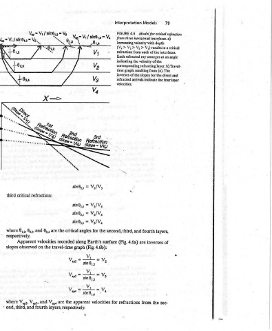
79   Model for  critical  refraction   -   depth   a  critical   interfaces.   an  angle   (a).  The   direct  and   layers,   of   e   sec-

          Models   from  three  horizontal  interfaces.   V))  results  in   of  the   each   ray  emerges  at   velocity  of  the  corresponding  refracting  layer.  b)  Travel-   refracted  arrivals  indicate  the  four  layer   fourth   inverses   are   the   from

          Interpretation   FIGURE   4.6   Increasing  velocity  with   V2 >   V3 >   >   (V,   refraction   --   from   Each  refracted   indicating  the   time  graph  resulting  from  inverses  of  the  slopes  for  the   velocities.   second,  third,  and   4.6a)   (Fig.  surface   refractions   for


                 &,  Vop  =Vi/  sin®,4™  Vs   B14   ee                V./V3   =   sin®,,   V,/V,   =  sin®,,   V2/V,   =   sin®,,   V3/V,   =   sin®,,   the   for  angles   Earth’s   along   4.6b):   (Fig.   graph   Vv   Vv,  =—l=   sin®,,   Vv   =   =   Vs   sin  ®, 5   V;  Vi4=—+=V  4   se,   velocities  apparent   &


              =  Va   8)...   =                                                        critical   the   recorded   travel-time   Vapo   V  *p3   mw   the   are   layers,  respectively.
              Sin8y3   Mia   Sis   NX                                                  are   the                 V,,,

             Vs /                                                         refraction:   6,   and   velocities   on   and   fourth
             Vap  =   Var   *                                                          8,3,   observed           Vap3,   and

                 sin®y2                                                   critical     8, »,   respectively.   Apparent   V9,

                 V1 /                                                     third        where   slopes            where   ond,  third,
                 Vap  =                                                                                            -


                                                                         required  spreadlengths      determined  graphs  were   deeper   a   of  velocity   the   4.6).   Fig.   in   V,   >   V,   >   V,   >   deeper   and  deeper  crosses   it   Rays  (Fig.  4.6a).  refracting  layer   than  angles  higher   at  emerge   corresponding  velocities   interfaces.  shallow   with   to  according  interfaces,


          Interpretation                                                 times  (t,),  crossover  distances  (X,,),  and   (c)  deep.  Trave]-time  moderate;  (b)  shallow;  and   text.   where  interfaces,  horizontal   (V,   above   layer   of  the   as  horizontal   the  toward   the  critically  along   depth   at  interface   apparent   the  refractors;   associated   those  higher  than   successive   across  bends   ray   V,/V2   =   sin®,,   V;/V3   =   sin®,,


          Refraction                                                               Interfaces   several   that   than   more   horizontally   higher-velocity  shallow,  lower-velocity   thus   refracted


          Seismic                                                        Approximate  T-axis  intercept   are  (a)   that  modeling  equations  presented  in   of   case   the   greater   always   and   more   a   along   are  refractors   critically   (Fig.  4.6a):   refraction:   refraction:  critical


          Chapter4                                                       4.5  for  bedrock  depths  (h)   using  forward   Horizontal   Consider   is   layer   bends   ray   A   interfaces,  traveling   refracted   from   those   deep   to   Each   Law   Snell’s   critical   first   second


          78                                                             FIGURE    Several