
Page 412 - Wind Energy Handbook
P. 412
386 COMPONENT DESIGN
reduces over time during a fatigue test – hence the need to specify that the strain
range is measured at the start of the test.)
The fatigue behaviour of composites depends on both the stress range and the
mean stress level, which can both be described in terms of the maximum stress,
ó max , and the ratio of minimum to maximum stress, R. It is convenient initially to
consider fatigue behaviour under reverse loading, i.e., with R ¼ 1, for which the
mean stress is zero, and then relate behaviour at other R ratios to it.
The constant amplitude fatigue behaviour of glass-fibre composites can best be
characterized by a linear relationship between the logarithm of the number of cycles
and the logarithm of the stress or strain amplitude, viz:
å ¼ å 0 N 1=m or N ¼ Kå m where K ¼ (å 0 ) m or log N ¼ log K m log å (7:6)
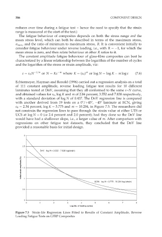
Echtermeyer, Hayman and Ronold (1996) carried out a regression analysis on a total
of 111 constant amplitude, reverse loading fatigue test results for 10 different
laminates tested at DnV, assuming that they all conformed to the same å–N curve,
and obtained values for å 0 , log K and m of 2.84 percent, 3.552 and 7.838 respectively,
with a standard deviation of log N of 0.437. The DnV regression line is compared
with another derived from 19 tests on a 08/þ458, 458 laminate at ECN, giving
å 0 ¼ 2:34 percent, log K ¼ 3:775 and m ¼ 10:204, in Figure 7.5. The researchers did
not constrain the regression lines to pass through the strain value at either UTS or
UCS at log N ¼ 0(ca 2.4 percent and 2.0 percent); had they done so the DnV line
would have had a shallower slope, i.e., a larger value of m. After comparison with
regressions on other fatigue test datasets, they concluded that the DnV line
provided a reasonable basis for initial design.
3
2.5
DnV: log N = 3.552 - 7.838 log(strain)
2
Initial strain amplitude (%) 1.5
1
ECN: log N = 3.775 - 10.204 log (strain)
0.5
0
0 1 2 3 4 5 6 7 8
Log (No. of loading cycles)
Figure 7.5 Strain-life Regression Lines Fitted to Results of Constant Amplitude, Reverse
Loading Fatigue Tests on GFRP Composites