
Page 467 - Wind Energy Handbook
P. 467
GENERATOR 441
The equations used to describe the steady-state performance of induction gen-
erators are given in any standard undergraduate textbook (e.g. Hindmarsh, 1984,
and McPherson, 1990). Dynamic analysis is more complex but is dealt with by
Krause (1986).
7.5.2 Variable-speed generators
There are two fundamental approaches to electrical variable-speed operation. Either
all the output power of the wind turbine may be passed through the frequency
converter to give a broad range of variable speed operation or a restricted speed
range may be achieved by converting only a fraction of the output power.
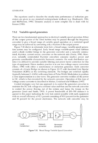
Figure 7.32 shows in schematic form how a broad range, variable-speed genera-
tion system may be configured. Early broad range variable-speed wind turbines
used a diode rectifier bridge in the generator converter and a naturally commu-
tated, thyristor, current source, converter on the network side (Freris, 1990). How-
ever, naturally commutated thyristor converters consume reactive power and
generate considerable characteristic harmonic currents. On weak distribution sys-
tems it is difficult to provide suitable filtering and power factor correction for this
type of equipment. Hence modern practice is to use two voltage source converters
(Heier, 1998) with either a synchronous or induction generator. Each converter
consists of a Graetz Bridge (as shown in Figure 10.17) with Insulated Gate Bipolar
Transistors (IGBTs) as the switching elements. The bridges are switched rapidly
(typically between 2–6 kHz) with some form of Pulse Width Modulation to produce
a close approximation to a sine wave. The generator converter rectifies all the power
to DC, which is then inverted by the network converter. Operation of this type of
voltage source converter is described in Mohan, Undeland and Williams (1995).
Control strategies vary but one approach is to control the generator converter to
maintain the DC link voltage at a constant value and then use the network converter
to control the power flowing out of the system and hence the torque on the
generator (Jones and Smith, 1993). A power bandwidth of 200–500 radians/s is
quoted in this paper indicating the very fast control possible with such equipment
with an overall efficiency of 92.1 percent consisting of 95.9 percent for the generator
and 96 percent for the power electronics. The network side converter may be
Local Network Generator
transformer converter converter
Figure 7.32 Broad Range Variable Speed Generation