
Page 470 - Wind Energy Handbook
P. 470
444 COMPONENT DESIGN
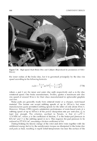
Figure 7.34 High-speed Shaft Brake Disc and Calliper (Reprodued by permission of NEG-
Micon)
the inner radius of the brake disc, but it is governed principally by the disc rim
speed according to the following formula:
3 þ í 1 í a 2
2 2
ó Ł (a) ¼ rø b 1 þ (7:58)
4 3 þ í b 2
where a and b are the inner and outer disc radii respectively and ø is the disc
rotational speed. One brake manufacturer, Twiflex, quotes a maximum safe disc
rim speed of around 90 m/s for their discs manufactured in spheroidal graphite
cast iron.
Brake pads are generally made from sintered metal or a cheaper, resin-based
material. The former can accept rubbing speeds of up to 100 m/s, but some
manufacturers quote permitted rubbing speeds for the latter of only about 30 m/s.
However, Wilson (1990) reports satisfactory performance of resin-based pads at a
rubbing speed of up to 105 m/s if the power dissipation rate per unit area, Q,is
kept low enough. The criterion, ascribed to Ferodo, is that Q ¼ ìPV <
2
11:6MW=m , where ì is the coefficient of friction, P is the brake-pad pressure in
2
KN/m and V is the rubbing speed in m/s. This requires the pad pressure to be
2
reduced to 275 KN/m , assuming a friction coefficient of 0.4.
During braking the kinetic energy of the rotor and drive train together with the
additional energy fed in by the aerodynamic torque are dissipated in the brake disc
and pads as heat, resulting in rapid initial temperature rise near the surface of the