
Page 473 - Wind Energy Handbook
P. 473
MECHANICAL BRAKE 447
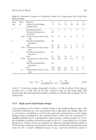
Table 7.6 Illustrative Example of Calculation of Brake Disc Temperature Rise Using Finite
Element Model
Time Time Element 0 1 2 3 4 5
step (s) Distance from braking 0 1.0 2.0 3.0 4.0 5.0
surface (mm)
1 Initial temperature 0 0 0 0 0 0
Boundary temperature 40
increment
0.025 Temperature at end of time 20 10 0 0 0 0
step
2 Boundary temperature 40
increment
Sum 60 10 0 0 0 0
0.05 Temperature at end of time 35 20 2.5 0 0 0
step
3 Boundary temperature 40
increment
Sum 75 20 2.5 0 0 0
0.075 Temperature at end of time 47.5 29.4 6.3 0.6 0 0
step
4 Boundary temperature 40
increment
Sum 87.5 29.4 6.3 0.6 0 0
0.1 Temperature at end of time 58.5 38.2 10.6 1.9 0.1 0
step
E 1 E 2ð
Ł max Ł 0 ¼ p ffiffi ¼ p ffiffi (7:63)
t 64 600w(D w) t 64 600S
where E is the total energy dissipated in Joules, t is the duration of the stop in
seconds and S is the area of the disc surfaces swept by the brake pads. The
temperature derived using this formula is plotted as a dotted line in Figure 7.35 for
comparison.
7.6.4 High-speed shaft brake design
A key parameter to be chosen in brake design is the design braking torque. The
coefficient of friction can vary substantially above and below the design value due
to such factors as bedding in of the brake pads and contamination, so the design
braking torque calculated on the nominal friction value must be increased by a
suitable materials factor. Germanischer Lloyd specify a materials factor of 1.2 for
the coefficient of friction, and add in another factor of 1.1 for possible loss of calliper
spring force. If these factors are adopted, the minimum design braking moment is
1.78 times the maximum aerodynamic torque, after including the aerodynamic load
factor of 1.35. A small additional margin of, say, 5 percent should be added to