
Page 475 - Wind Energy Handbook
P. 475
MECHANICAL BRAKE 449
(b) Brake-disc diameter selection: The maximum rotor speed corresponds to a high-
speed shaft speed of 21:9 3 (1500=19) ¼ 1729 r:p:m: ¼ 181 rad=s, so the maxi-
mum permissible brake-disc radius as regards centrifugal stresses is about
90=181 ¼ 0:497 m. It is advisable to choose the largest permitted size in order
to minimize temperature rise, so 1.0 m diameter is selected in this case. The
pad rubbing speed will be quite acceptable if sintered pads are used.
(c) Selection of number and size of brake pads: The total brake-pad area is governed by
the need to keep the maximum power dissipation per unit pad area below
2
11.6 MW/m . The power dissipation is equal to the product of the braking
torque and the rotational speed, so it is at a maximum at the onset of braking,
i.e. 22:8 3 181 ¼ 4128 kW, giving a required total area of the brake pads of
2
4128=11 600 ¼ 0:356 m . This area can be provided by four callipers fitted with
2
0:22 3 0:22 m pads, giving 0.387 m in all.
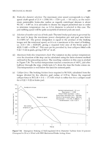
(d) Maximum brake-disc temperature check: The variation in disc surface temperature
over the duration of the stop can be calculated using the finite-element method
outlined in the preceding section. The resulting variation in this case is plotted
in Figure 7.36. The surface temperature reaches a maximum of 4408C, just after
halfway through the stop, which lasts 4.7 s from the time the brake comes on.
This temperature is well below the limit for sintered pads.
(e) Calliper force: The braking friction force required is 58.5 kN, calculated from the
torque divided by the effective pad radius of 0.39 m. Hence the required
calliper force is 58:5=(8 3 0:4) ¼ 17:3 kN which is rather low for a calliper sized
for a 0:22 3 0:22 m brake pad.
1000 25
Aerodynamic torque
900
Nominal rotational speed = 19 r.p.m.
Rated power = 1.3 MW
800 Rotational speed Brake torque referred to LSS = 1800 kNm 20
Delay in brake application = 0.35 s
Torque (kNm) and temperature rise ( C) 600 temperature rise Disc diameter = 1.0 m, No. of callipers = 4 15 Rotational speed (r.p.m.)
700
Maximum aerodynamic torque = 966 kNm
Pad dimensions = 0.22 x 0.22 m
500
Disc surface
10
400
300
200 5
100
0 0
0 1 2 3 4 5 6 7 8
Time (s)
Figure 7.36 Emergency Braking of Stall-regulated 60 m Diameter Turbine from 10 percent
Overspeed in 20 m/s Wind with HSS Mechanical Brake Acting Alone